CNC Lathe Workholding Selection: Chuck, Collet, Tailstock or Steady Rest
By HORISTAR · Updated September 23, 2026
Choose lathe workholding from the part and the cutting forces, not from the machine’s maximum swing or chuck diameter. A self-centering three-jaw chuck, often hydraulically actuated, may be the fastest route for a mixed batch. A collet may be better for repeatable bar work. A tailstock or steady rest may be necessary when a long shaft fits in the envelope but deflects under the tool.
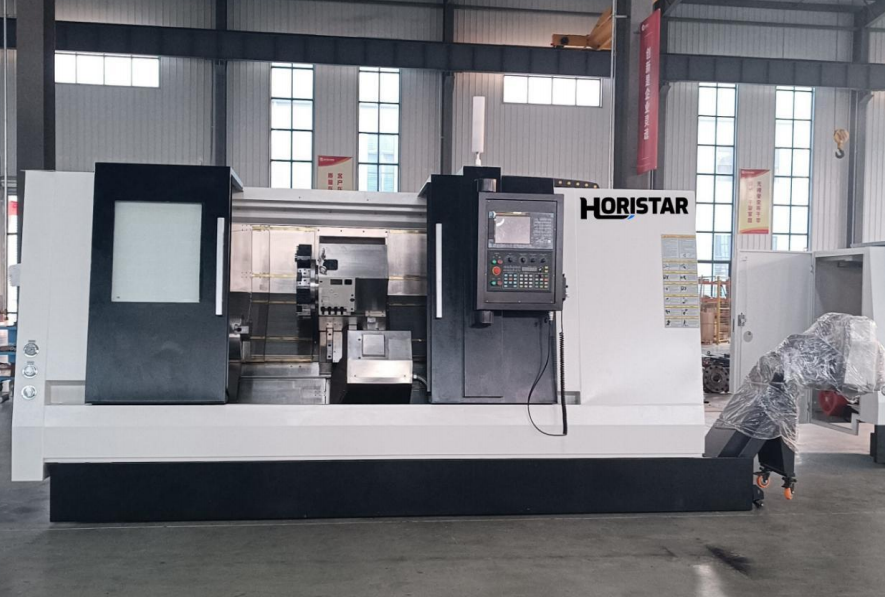
The correct setup must hold the part securely, locate it repeatably, leave the tool access that the program needs and keep runout within the drawing tolerance. It also has to load at the pace of production. A fixture that is accurate but slow can be the wrong choice for a high-volume part; a fast fixture that distorts a thin wall can be the wrong choice for every part.
Key takeaways
- Separate how the part is gripped from how the chuck is actuated. A three-jaw, four-jaw or collet describes the gripping geometry; hydraulic or pneumatic power describes the actuation.
- A tailstock live center and a steady/follow rest are supports. They supplement a primary chuck or collet; they do not replace the locating datum.
- The useful result is a setup drawing with grip length, datum, support position, tool access and measured runout—not a catalog chuck diameter.
- Published chuck runout examples are reference conditions. Your contract value must come from the actual jaws/collet, blank, pressure, re-grip method and finished feature.
Quick selection table
| Workholding route | Best starting case | Main limitation to check |
|---|---|---|
| Power-actuated three-jaw chuck | Round or hexagonal parts with changing diameters and quick loading | Jaw condition, gripping length, clamping deformation and runout |
| Collet chuck | Repeated bar diameters, small parts and a high loading rate | Limited diameter range, part-shape restrictions and bar-quality requirements |
| Tailstock with live center | Long or slender shafts that need axial support from the rear | Centre hole, tailstock access, tool clearance and whether the support follows every operation |
| Steady rest or follow rest | Long slender work where radial support is needed near the cutting zone | Support location, access to the surface, setup time and contact with the finished area |
| Independent four-jaw chuck | Irregular, eccentric or deliberately offset work | Manual indicating time and operator skill |
These are starting directions. The actual choice depends on the drawing, blank condition, tolerance, toolpath, material and production volume.
Separate grip geometry from actuation
“Hydraulic chuck” is not a fourth gripping geometry. It normally describes a power-actuated chuck, often with three or four jaws. A collet chuck can also be actuated through a drawtube or another power system. Put both decisions in the RFQ:
- Grip geometry: three-jaw self-centering, four-jaw independent, collet, soft jaws, expanding mandrel or another fixture.
- Actuation: manual, hydraulic, pneumatic or another approved drive, including pressure monitoring and the safe speed range.
This distinction prevents a common quotation error: selecting a large power chuck while leaving the jaw profile, contact length and pressure undefined.
Start with the finished part and the incoming blank
Before discussing a chuck, mark the features that control the setup:
- Which diameter or bore is the primary datum?
- Which surfaces must remain concentric after a second operation?
- What is the unsupported length during roughing and finishing?
- Where must the tool, boring bar, drill or tailstock enter?
- Does the blank arrive round, hexagonal, forged, cast or welded?
- Will the same part be loaded once, or will it be re-gripped between operations?
The finished length is not the same as the usable turning length. Chuck jaws, a backstop, the tailstock and the tool turret all consume space. HORISTAR’s long-shaft application guide makes the same point: a shaft can fit inside a lathe and still be unsuitable when the chuck, supports, tools and access are considered together.
For the full machine envelope, compare this guide with HORISTAR’s long-shaft CNC lathe application guide and the TCK CNC lathe product page. The product page supplies machine context; the drawing and sample part decide whether the setup works.
After the workholding route is selected, pair the test with HORISTAR’s CNC lathe pre-shipment acceptance checklist and the turret repeatability and surface-finish test guide.
When a self-centering three-jaw chuck is the right answer
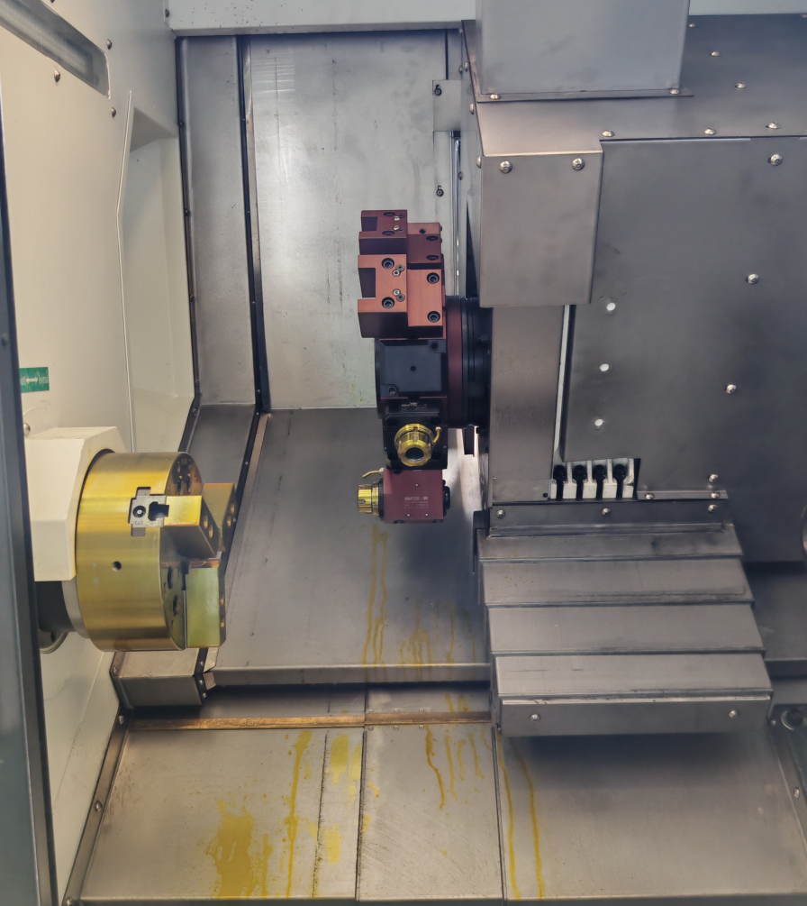
A self-centering chuck is a strong default for round or hexagonal parts when fast loading matters. Hydraulic actuation gives a repeatable clamping cycle and makes automation easier. It is well suited to sleeves, flanges, fittings and general batch turning when the gripping diameter changes within the chuck’s rated range.
Check four details before accepting the default:
- Grip length: enough jaw engagement is needed for the cutting force and the material condition. A short grip can let the blank move even when the chuck is large.
- Soft jaws: fresh bored soft jaws can improve repeatability for a recurring diameter. Hardened standard jaws are convenient, but their condition and contact pattern still affect runout.
- Thin-wall deformation: high pressure can distort a ring or tube. Set pressure from the chuck and machine manufacturers’ required gripping force at the intended spindle speed, with the specified safety margin for the workpiece, jaws and cutting load. Verify secure gripping and part deformation; do not reduce pressure below the approved range to solve distortion.
- Second-operation location: if the part returns to the chuck, define the locating face and bore/diameter that will be used. “Self-centering” does not guarantee the runout required by every drawing.
UTEC’s workholding reference describes manual three-jaw scroll chucks: they center regular shapes quickly, while wear in the scroll and jaws can become the limiting factor for precision work. This scroll-wear explanation does not describe every hydraulic power-chuck mechanism. The useful lesson is not a universal runout number; it is to treat chuck condition, soft jaws and the required datum as part of the process.
The UTEC workholding reference publishes general-reference estimates for manual scroll-chuck setups: roughly 0.005–0.015 in runout for a production three-jaw, and roughly 0.001–0.002 in with freshly bored soft jaws for a recurring diameter. These are the source’s reference estimates, not independently verified test results or specifications for a modern hydraulic chuck. These are not HORISTAR guarantees. Use them to ask what the supplier will measure and which jaws, blank and datum were used.
When a collet is better
A collet is worth evaluating when the production part is a repeated bar diameter, the stock is prepared consistently and fast loading or low radial deformation matters. The contact is distributed around the bar, and a properly selected collet can give a repeatable grip without the jaw marks that a small finished diameter may show.
Do not choose a collet only because it is more precise in a catalog. Confirm:
- the actual diameter range and tolerance of the incoming bar;
- whether the profile is round, hexagonal or another supported shape;
- the usable gripping length and bar-stop arrangement;
- the runout requirement at the finished feature;
- the time and cost of changing collets between part families;
- how chips and coolant will be cleared from the collet nose.
For a high-mix shop, a hydraulic chuck with a sensible soft-jaw and backstop plan may deliver more useful capacity than a collet system that needs frequent changeovers.
When the tailstock is necessary
A live center in the tailstock supports the work along the spindle axis. It is most useful when the part is long enough that the tool force would bend the blank away from the tool, or when the operation removes a large amount of material before the final pass. Both fixed and live centers require suitable, properly prepared center contact; a standard pointed center normally uses a center hole. A live center rotates with the work on bearings and is often used in production setups.
The center is not a substitute for a good primary grip. Confirm that:
- the blank has a suitable center hole or that one can be made without damaging the datum;
- the tailstock can reach the part without blocking the turret or tool change;
- the center load will not deform a thin wall or interfere with a bore;
- coolant, chip evacuation and the final facing operation remain possible;
- the support remains valid after each re-grip.
For a shaft with a changing end feature, define the operation sequence before buying the machine. A center that works for rough turning can become an obstruction during drilling, grooving or thread work.
When a steady rest or follow rest is necessary
A steady rest supports the work radially at a selected location. A follow rest travels with the tool. Either becomes important when the unsupported length is large compared with the diameter, when the part is flexible, or when a deep boring or heavy roughing operation creates too much deflection for the primary grip and tailstock center alone.
The support position should follow the force, not simply the midpoint of the part. Check the tool approach, the finished surface, lubrication of the support pads and whether the rest can move to the next operation. A follow rest travels with the tool and can support a slender feature during turning; a fixed steady rest supports a selected diameter while the tool works elsewhere.
If the rest touches a surface that later becomes a datum, define the contact allowance and cleaning method. A support that prevents deflection but marks the finished reference surface has only moved the problem.
A practical decision path
Use this sequence for a new part:
- Classify the blank: round bar, tube, forged blank, casting or weldment.
- Choose the primary datum: the surface or bore that must be located first.
- Choose the primary grip: chuck for flexibility, collet for repeated bar work, or an independent chuck for irregular/eccentric geometry.
- Calculate the unsupported section: compare length, diameter, material stiffness and the planned roughing force.
- Add axial or radial support: center, steady rest or follow rest only where it improves the actual cutting operation.
- Check access: simulate the turret, boring bar, drill, chip flow and tool change with the support installed.
- Define the acceptance test: runout, size, taper, surface finish, cycle time, loading time and part marks.
The decision should produce a setup drawing or a short fixture note. It should show the jaw/collet contact, backstop, center or rest location, supported length and the features that will be measured.
When the tool force pushes unsupported work away from the cutting edge, the result is often taper because one end of the part is cut more heavily than the other. When clamping pressure exceeds thin-wall stiffness, the part can spring back after unclamping. That is why the setup drawing and the free/clamped measurements belong in the acceptance record.
A simple screening calculation
Use the ratio L / D (unsupported length divided by the supported diameter) only as a screening flag. It is not a universal steady-rest threshold. A long aluminum shaft, a short hardened-steel shaft, a deep boring bar and a high-force roughing pass can produce different outcomes at the same ratio. When the ratio or the cutting force raises concern, compare the predicted deflection with a trial cut and measure the taper at both ends.
Sample-test checklist before purchase
The following is a proposed repeatability plan, not a universal tolerance: 3 representative parts, 2 re-grips when a second operation is required, and 4 measurement states for a thin wall (free, clamped, finished while clamped, and free after unclamping).
| Test | What to record |
|---|---|
| Loading | Time from blank presentation to cycle start; operator steps; changeover time |
| Location | Datum used, backstop repeatability and re-grip method |
| Runout | Chuck/collet indication and finished-part runout at the important features |
| Deflection | Tool-side and tail-side measurements during roughing and finishing |
| Surface condition | Jaw marks, collet marks, center marks and rest-pad marks |
| Access | Boring, drilling, threading, grooving, tool change and chip evacuation |
| Repeatability | Several repeated parts, not one demonstration part |
| Evidence | Measurement report, program revision, tooling list and setup photographs |
Ask the supplier to run a representative part with the proposed chuck, jaws, collet, center and rest. A generic test bar cannot answer whether your actual shaft, thin ring or flange will remain accessible and stable.
Thin-wall and re-grip measurement plan
For a thin ring or tube, measure the part in four states: free before clamping, clamped before cutting, finished while clamped and free after unclamping. Record the chuck/collet type, contact length, actuation pressure and jaw/collet ID. Repeat the sequence on three parts and, when a second operation is required, repeat the re-grip measurement twice per part. This is a proposed acceptance design, not a universal tolerance; set the pass/fail value from the drawing.
For runout, measure at the chuck, at the locating datum and at the finished feature. A self-centering chuck can locate quickly while still missing the finished-part concentricity requirement if the datum, jaws or soft-jaw bore are wrong.
Troubleshooting common workholding problems
| Symptom | First checks |
|---|---|
| Taper on a long shaft | Support position, center alignment, tool force, guideway condition and whether the part is lifting from the support |
| Runout changes after re-gripping | Datum choice, soft-jaw bore, jaw contact, chip contamination and clamping pressure |
| Thin wall becomes oval | Pressure, contact length, jaw profile, collet size and the sequence of roughing passes |
| Vibration appears only during roughing | Unsupported length, tool overhang, support location, insert geometry and the actual gripping length |
| Good first part, poor later parts | Jaw/collet contamination, thermal growth, bar variation and a support that is wearing or losing preload |
| Cycle is accurate but too slow | Loading steps, collet changeovers, center approach, rest positioning and automation access |
Frequently asked questions
When is a collet a poor choice?
When the incoming diameter varies outside the collet range, the profile is irregular, the family changes often, or the part needs a grip position that a collet cannot reach. A collet is not automatically better for a high-mix job.
Does a steady rest replace a chuck?
No. The chuck or collet establishes the primary location and transfers cutting torque. The steady or follow rest controls radial movement near the cut. Both must leave the toolpath and finished surfaces accessible, and the support must not become the only datum for a second operation.
Why can a steady rest leave marks?
The pads contact a rotating surface under load. Excessive preload, chips, poor lubrication or contact on a finished datum can transfer marks or heat. Measure the contact surface after the trial and define the cleaning or allowance in the setup.
Can soft jaws solve every runout problem?
No. Soft jaws address one recurring diameter and one clamping condition. They do not correct a bad datum, a bent blank, chip contamination, a worn chuck body, an incorrect pressure or a feature that is not concentric to the gripping surface.
Final recommendation
Select the chuck, collet, center and rest as one workholding system. The best answer is the one that keeps the datum repeatable, controls deflection, leaves the toolpath accessible and meets the production loading time. Send the part drawing, blank condition, tolerance, surface-finish requirement, monthly volume and representative cycle to HORISTAR before asking for a final CNC lathe configuration.
Sources
- HORISTAR Integral High-Low Rail Bed CNC Lathe — current TCK-series product and application context.
- HORISTAR: Choosing a CNC Lathe for Long Shafts — explains why usable space, tailstock/steady-rest locations and process access must be reviewed together.
- UTEC: Lathe Chuck Types—3-Jaw, 4-Jaw, Collet, and Faceplate Selection — describes the geometry, accuracy and production-volume trade-offs among common chuck types.
- Haas Tooling: CNC Lathe Workholding — current manufacturer tooling catalog for lathe workholding options.
- Röhm KFD-HE power-chuck manual, hosted by Haas — gripping force, jaw mass, rotational speed and operating limits.
- HORISTAR CNC Lathe Pre-Shipment Acceptance Checklist — related checks for chuck, hydraulic system, trial cutting and dimensional acceptance.