Workholding & machine selection
Choosing a CNC Lathe for Long Shafts: Turning Length, Tailstock and Steady Rest
Select the working envelope and support arrangement together.
Read the guide
SpaceBlank, chuck and tool access
SupportTailstock and rest locations
EvidenceA representative trial part
A long shaft can fit inside a lathe and still be unsuitable for the proposed production setup. The chuck and jaws take space, the tailstock needs access, the cutting tool must reach the features, and the workpiece needs support while material is removed. A nominal length rating answers only part of the selection question.
Choose a CNC lathe for long shafts by reviewing usable space, support locations, process access and part-quality evidence together. The supplier should be able to show where the actual blank, holders and supports sit during each operation. A larger bed is useful only if the complete arrangement works.
Begin with the shaft drawing and the incoming blank
Send both the finished-part drawing and the starting-stock condition. The support arrangement may depend on a surface that does not yet exist on a rough blank, or that disappears later in the machining sequence.
Identify the longest part, the smallest section that will remain during cutting, the major diameter steps and the features requiring access from each end. Include center-hole requirements or restrictions. A shaft with no permitted center hole needs a different discussion from one designed for machining between centers.
| Input | Why it matters |
|---|---|
| Finished and blank lengths | Establishes the physical setup and machining allowance |
| Diameter profile | Identifies slender sections, shoulders and potential support journals |
| Material and condition | Informs machining, workholding and handling review |
| Critical drawing requirements | Defines what must be demonstrated on the finished part |
| Center holes and end features | Determines whether tailstock support conflicts with machining access |
| Blank straightness and surface condition | Helps evaluate clamping and the first support operation |
| Batch size and loading method | Connects the support design to production handling |
The overall length-to-diameter ratio is a useful description, but it does not capture every stepped shaft. Record the unsupported span and local diameter at each operation. Avoid using one universal ratio as proof that a tailstock or steady rest is unnecessary.
Convert nominal length into a usable layout
Ask the builder what its published length dimension measures. Maximum workpiece length, maximum turning length, distance between centers and Z-axis travel are related dimensions, but they should not be treated as interchangeable.
The HORISTAR CNC lathe page lists workpiece-length ranges of 500–1,000 mm for TCK56Y and 1,000–3,000 mm for TCK63Y/TCK80Y. These are published configuration ranges, not a guarantee that every machine in the family processes every length with any tooling arrangement. [1]
Request a layout for the quoted bed length and equipment. It should show the chuck face and jaws, gripped portion of the blank, tailstock body and center, steady-rest body if required, and the mounted tools at their critical positions.
For an illustrative RFQ, consider a 1,200 mm finished shaft made from a 1,240 mm blank. Neither dimension alone determines the required machine length. The supplier still needs the gripping arrangement, end preparation, tool approach and support positions. A “1,200 mm part” should not automatically be assigned to a machine with a similarly labeled catalogue dimension.
Also review the loading route. A shaft that fits during cutting may still be difficult to insert, unload or transfer around a support arm or enclosure opening.
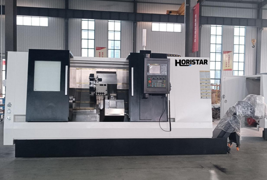
Complete HORISTAR CNC lathe. An exterior machine photo cannot establish usable turning length with a particular chuck, tailstock and tooling package.
View the source product pageMatch the support to the operation
A tailstock supports the end of the workpiece through a suitable center arrangement. A steady rest supports the outside of the workpiece at a selected location. They can be alternatives for a particular operation or parts of the same process, depending on access and the approved setup. Manufacturer documentation describes these distinct support functions. [2]
Use the following matrix to prepare the applications discussion, rather than as a machine-setting instruction.
| Process situation | Support question to resolve |
|---|---|
| External turning with a usable center hole | Can tailstock support provide the required stability and tool access? |
| End drilling or boring conflicts with the center | What support arrangement keeps the workpiece controlled while the end is accessible? |
| A slender span remains far from end supports | Is additional support near a suitable journal required? |
| A diameter under a support must be machined | How will the process transfer support before cutting that surface? |
| A rough or irregular blank has no suitable contact surface | How will the first support journal be prepared and verified? |
| Steps or shoulders interrupt the contact path | Can the chosen support geometry accommodate the full sequence? |
Do not assume that removing the tailstock to reach an end feature leaves an acceptable workholding condition. The alternative must be planned before that operation begins.
Check what the steady-rest option actually includes
“Steady-rest ready” and “supplied with an integrated steady rest” may describe different packages. Ask whether the quotation includes the rest itself, mounting equipment, actuation, lubrication, position monitoring and the control integration needed for the proposed sequence.
SMW-AUTOBLOK lists steady-rest variants with different body sizes, opening arrangements, position-monitoring provisions and chip/coolant features. Those distinctions matter to loading and integration; they should be specified rather than assumed from the accessory name. [3]
For the proposed part, request confirmation of the support diameter range, contact location, rated operating limits, access around the arms and protection of the finished surface. If the workpiece is supported at multiple stages, mark those stages on the drawing.
A bed provision does not establish compatibility with a particular rest. Nor does a quoted rest diameter range establish that its body clears the turret and chuck in the intended setup.
Treat tailstock force and alignment as process variables
Tailstock support must match the part and the installed equipment. Do not copy another manufacturer's pressure value into the setup sheet. Supply pressure is not a universal statement of force at the center, and the permitted settings depend on the mechanism.
Haas's hydraulic-tailstock troubleshooting guide discusses alignment, support pressure and part-quality symptoms. It illustrates that tailstock setup can affect the result; it does not provide HORISTAR operating settings. Use the delivered machine's manual and the approved sample process. [4]
When quality changes along the shaft, retain the measurement locations and the support state used during cutting. A single diameter reading at one end cannot explain what happened across the complete part.
Also distinguish workpiece-support problems from installation problems. Bed leveling and machine geometry belong in the installation record; the support arrangement belongs in the part setup. The existing new-lathe installation and leveling guide covers the former scope.
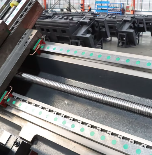
Linear guideways and ball screw shown on the HORISTAR product page. This is a motion-system detail, not a steady rest; confirm the workpiece-support arrangement independently.
View the source product pageAsk for a trial that represents the difficult part of the job
A short, rigid demonstration piece does not establish performance on your long shaft. Agree a trial using a representative drawing, material, blank condition and support arrangement. If a substitute part is necessary, document what it demonstrates and which requirements remain unproven.
An effective trial record connects each result to the setup:
| Trial record | Required detail |
|---|---|
| Part identity | Drawing revision, material and blank condition |
| Workholding | Chuck/jaw arrangement, grip and support locations |
| Tooling | Relevant holders, tool projection and operation sequence |
| Support state | Tailstock/steady-rest arrangement for each operation |
| Measurements | Features, locations, instruments and drawing requirements |
| Thermal context | When measurements were taken relative to machining |
| Production handling | How the part was loaded, supported and unloaded |
Specify diameter, form, runout, surface finish or other requirements exactly as the drawing defines them. These are different measurements. Do not substitute a general machine-positioning claim for finished-part evidence.
For a long batch, agree how the trial will represent the intended operating conditions. Record changes to tools, supports and offsets so that a good result can be reproduced. Any dimensional limits and acceptance sample sizes should be agreed for the job; the checklist itself is not a universal acceptance standard.
Include handling and rotating-stock limits in the RFQ
Long workpieces need a loading and support plan as well as a cutting plan. Identify the lifting method, access space and any stock extending through the spindle. Protruding rotating stock requires a manufacturer-approved support and guarding arrangement; it should not be left unsupported behind the machine.
Ask the builder to confirm operating limits for the complete workholding assembly, including the chuck, center, rest and workpiece. A maximum spindle speed in a catalogue does not establish an appropriate speed for a particular long-shaft setup.
Frequently asked questions
Is a longer-bed lathe enough for long shafts?
No. It must also provide usable travel and clearance with the actual workholding, tools and supports. Request a layout that demonstrates the complete setup and loading route.
Do all long shafts require both a tailstock and a steady rest?
No. The support arrangement depends on geometry, unsupported spans, cutting operations and access. The process may use one support type or a combination at different stages.
Can a steady rest contact an unfinished surface?
That depends on the rest design and the blank's condition. Do not assume an irregular surface is acceptable. Have the supplier define any preparation needed for the support journal and how the first operation will be held.
Can I choose a machine from maximum workpiece length alone?
Use it for initial screening, then verify the exact length definition and mounted layout. The practical machining envelope can change with chuck jaws, tool reach, tailstock position and support equipment.
Request a drawing-based long-shaft review
Contact HORISTAR with the finished drawing, blank dimensions, material, expected volume and the most difficult feature. Ask for a proposed machine configuration, support layout and representative trial plan. Confirm available tailstock and steady-rest options in writing for the quoted machine.
References
- HORISTAR — CNC Lathe Machine. Published length ranges checked on 2026-09-09; exact delivered configurations require quotation confirmation.
- Haas — Manual Lathe Operation. Reference for the basic roles of tailstock and steady rest, not CNC control commands.
- SMW-AUTOBLOK — Self-centering Steady Rests for Turning and Grinding. Manufacturer examples of support and integration features.
- Haas — Hydraulic Tailstock Troubleshooting, TG0088. Manufacturer-specific discussion of alignment, support and machining symptoms. Do not transfer settings between machines.