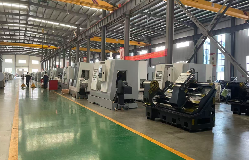
A new CNC lathe can be mechanically sound and still produce taper, changing diameter or unstable surface finish if the installation allows the bed to twist. Leveling is therefore not a cosmetic floor operation. It is the first geometric adjustment that connects the foundation, leveling hardware, bed, guideways, spindle and axis travel.
The useful acceptance question is simple: does the machine hold its geometry after the axes travel, the anchors are loaded, the coolant system is installed and the machine reaches operating temperature? A single bubble reading at the centre of travel cannot answer that question.
CNC Turret Lathe Installation Sequence: Geometry Must Survive Every Step
This guide gives buyers and commissioning teams a practical sequence for a newly installed CNC lathe. It separates three decisions that are often mixed together:
- Foundation decision: can the floor and support system carry the machine without unacceptable movement or vibration?
- Leveling decision: can the bed be adjusted without introducing twist as the axes move?
- Alignment decision: do the linear and rotary geometry checks meet the tolerance agreed for the machine and application?
Use this sequence as the commissioning backbone. Each step is a handoff between a physical condition and an evidence item.
Nine handoffs from foundation confirmation to a signed handover record — skipping one removes evidence, not risk.
If a supplier proposes to skip a step, ask which risk is being removed and where the replacement evidence will appear. “The machine is level” is not a replacement for a repeatable report.
Foundation Stiffness Beneath a CNC Turret Lathe
The foundation does not need to be judged by thickness alone. The installation team should understand the machine mass, support-point pattern, cutting forces, acceleration and braking loads, nearby vibration sources, floor joints and the intended anchoring method.
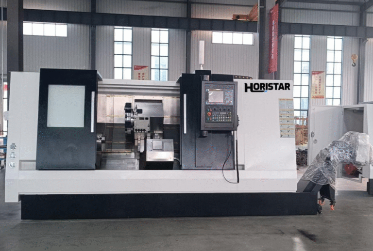
Before the machine arrives, request the model-specific layout drawing and installation manual. Confirm:
- Machine footprint and support-point locations.
- Coolant tank, chip conveyor, electrical cabinet and service-clearance zones.
- Slab construction, joints, embedded services and any isolated foundation block.
- Access route and lifting method, including temporary loads.
- Whether the OEM requires anchors, leveling pads, grout or a combination.
- Whether a local structural or seismic review is required.
Anchoring is not a substitute for a suitable foundation. The machine supplier defines its hardware, while the site engineer remains responsible for building and structural design.
A simple load-path worksheet
The following is a scoping worksheet, not a final structural calculation. It helps the buyer ask for the right information before a quote is frozen.
| Item to confirm | Why it changes the installation decision | Evidence to request |
|---|---|---|
| Machine mass and centre of gravity | Changes support reactions and lifting/placement risk | OEM layout and mass data |
| Support-point pattern | Determines where leveling screws, pads or grout transfer load | Foundation drawing with point locations |
| Cutting and acceleration loads | Indicates whether movement or rocking is a risk | Machine duty, axis acceleration and process description |
| Slab thickness, strength and joints | Determines whether drilling, isolation or a new foundation is appropriate | Site structural record or engineer review |
| Anchor type and load path | Prevents a bolt from being treated as a generic tie-down | OEM anchor drawing, hardware and installation method |
| Nearby vibration sources | Affects surface finish even when the machine itself is level | Presses, compressors, traffic and neighbouring equipment map |
For an early estimate, teams sometimes distribute a design overturning moment across the engaged anchors using a lever arm. Do not use that shortcut as a final anchor design: the actual stiffness of the bed, pad, grout, concrete edge distance and anchor installation governs the result. Include the responsible structural engineer in the approval record when the environment is demanding.
Anchor Holes and Loads for a CNC Turret Lathe
Anchor-hole size, depth, cleaning method and cure time are specific to the released machine drawing, the approved anchor system and the verified site structure. Do not transfer dimensions or torque values from another OEM or machine model.
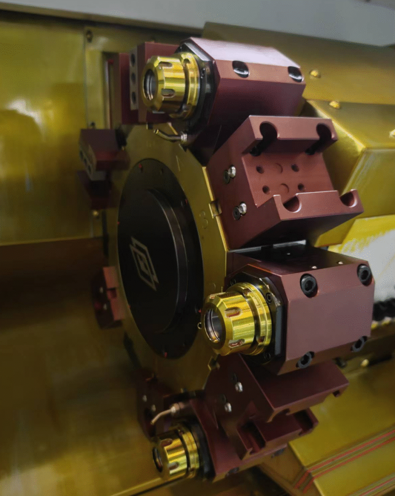
Installation cleanliness still matters. Prepare each hole exactly as the approved anchor manufacturer requires, record the product batch and ambient conditions, and respect the stated cure time before loading the machine. Plan the machine move, production stop and re-leveling window around the released installation procedure.
Control the anchor load path
Use this order when reviewing anchors:
- Confirm the hole pattern. Use the released machine layout drawing, not a scaled image or a previous model.
- Inspect the concrete. Check slab thickness, edge distance, cracks, joints and embedded services before drilling.
- Prepare the hole. Remove dust, oil and water. Record the cleaning method.
- Set the anchor assembly. Keep the stud perpendicular and protect the thread from contamination.
- Respect cure time. Record epoxy batch, ambient condition, installation time and release time.
- Load the machine gradually. Use the OEM sequence and specified torque increments; do not substitute a guessed torque value.
- Re-level after loading. Anchor tension can change the support reactions and introduce bed twist.
Leveling a CNC Turret Lathe Through Full Axis Travel
1. Calibrate the precision level before touching the machine
Reid Supply’s published machine-leveling procedure recommends checking a precision level on another machine, allowing it to settle for about five minutes, then flipping it 180 degrees and checking again. Use that as a practical field-control step. If the reading changes materially after the flip, resolve the instrument condition before recording machine data.
Keep the level, temperature, operator and instrument identification in the commissioning record. A bubble position without the instrument context is difficult to reproduce.
2. Bring the machine to a neutral load state
Place the axes at the centre of their travel before the first leveling pass. Remove transport restraints and confirm that the bed, turret, tailstock, chip conveyor and coolant tank are in the condition specified by the OEM. A machine that is partly supported by a temporary transport device cannot produce a useful geometry baseline.
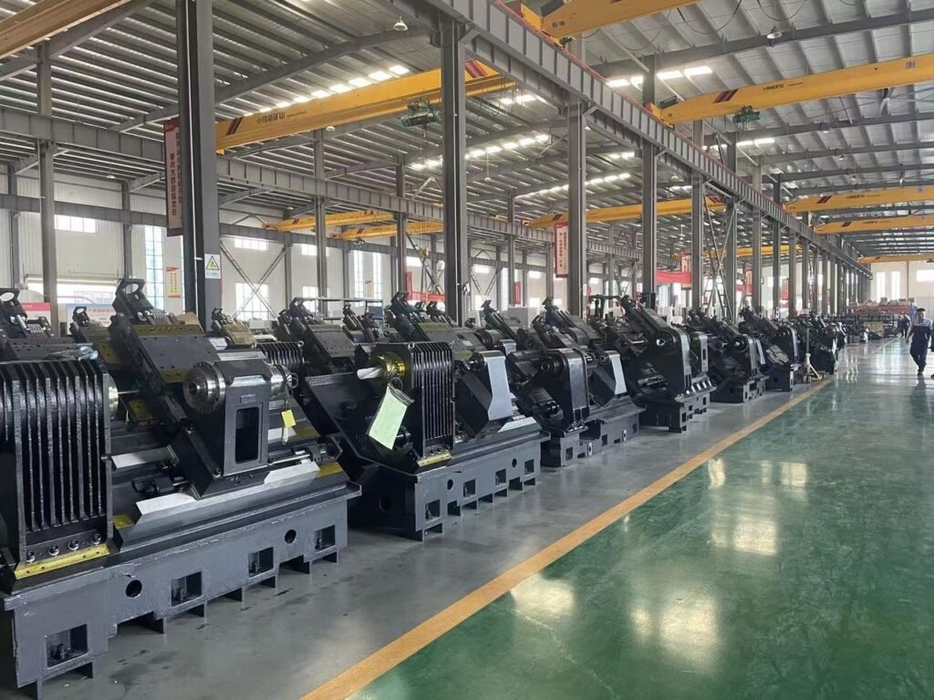
3. Use two directions and repeat the reading
Place one precision level parallel to the ways and another perpendicular to them, when the machine design permits. The two readings separate longitudinal slope from cross-bed slope. Adjust leveling screws in small, documented steps; after each adjustment, allow the reading to settle and record the new position.
4. Move through the complete stroke
After the centre reading is stable, move the relevant axis toward the positive end and then toward the negative end. Return to centre and compare the readings. A change that follows axis position can indicate bed twist, support-point movement, a loose leveling element, contamination under a pad or an instrument problem.
Do not accept the centre reading merely because it is within a preferred value. The installation record should show the centre, positive-end and negative-end readings, the adjustment made and the person who approved the result.
5. Touch down auxiliary supports only after the primary geometry is stable
Cabinets, pallet changers, chip conveyors and other supports can introduce a second load path. Bring them into contact only as the OEM specifies, then repeat the key level and alignment checks. If a secondary support changes the reading, it is part of the machine’s geometry and must be included in the final record.
Laser Alignment for a CNC Turret Lathe
Laser equipment is not a magic pass/fail device. It is a way to make the geometric error visible and traceable over the machine length.
| Measurement | Buyer question | Typical evidence format |
|---|---|---|
| Level to gravity | Is the casting or reference plane tilted after support loading? | Instrument ID, setup sketch and readings by support point |
| Straightness | Do the carriage and guide references deviate along the axis? | Error plot with axis positions and environmental notes |
| Parallelism | Do paired ways or rails remain parallel through travel? | Two-line or paired-reference report |
| Squareness | Are linear axes geometrically orthogonal? | Squareness report with reference plane and direction |
| Flatness | Is a functional surface varying in height across the reference area? | Grid or point map with datum definition |
| Spindle direction/coaxiality | Is the rotary reference aligned with the linear geometry? | Rotary measurement record and acceptance tolerance |
Renishaw describes its XK10/XK20 systems as tools for straightness, parallelism, squareness, flatness, level and rotary measurements. Its published material states that XK10 measurements can cover machine-axis lengths up to 30 m with the relevant unit configuration, while the newer XK20 material references ISO 230-11 reporting and ISO 10791/3070 measurement tolerances. These are useful examples of a digital measurement workflow; the tolerance for your lathe must still come from the machine specification, customer drawing or agreed acceptance standard — the same principle used in HORISTAR’s own ISO 230-2 / ISO 13041 accuracy FAT.
Control the laser setup
- Stabilize the reference and document its mounting point.
- Record temperature, warm-up state, machine position and environmental changes.
- Use the same datum definition for the pre-adjustment and post-adjustment reports.
- Save the raw file as well as the exported PDF or screenshot.
- Recheck the first and last points after any support or anchor adjustment.
- Link each correction to a physical action, such as a named leveling screw or shim.
The objective is not to collect a colourful graph. It is to show which physical correction changed which geometric error, and whether the correction remained after the machine was reloaded and warmed up.
CNC Turret Lathe Acceptance Table and Release Evidence
Before delivery, agree the table below with the supplier and the site team. Replace “OEM tolerance” with the actual value from the released machine documentation; never fill it with a generic internet number.
| Checkpoint | Record | Release question |
|---|---|---|
| Foundation and placement | Slab condition, layout revision, support map | Is the machine on the released load path? |
| Precision-level verification | Instrument ID, settle time, 180-degree check | Is the instrument itself trustworthy? |
| Level at centre and both ends | Three positions, two directions, adjustment log | Does level remain stable through travel? |
| Anchor or pad installation | Hardware, hole record, cleaning, cure and torque sequence | Was the designed connection installed without contaminating geometry? |
| Laser geometry | Raw file, report, setup sketch, tolerance source | Are straightness, parallelism, squareness and level within the agreed limit? |
| Warm-up and test cut | Warm-up program, tool, material, dimensions and finish | Does the machine hold geometry under operating conditions? |
| Handover | Open items, owner, due date and recheck date | Can production and maintenance reproduce the released state? |
Failure Signatures and the First Correction to Investigate
| Symptom after installation | First areas to investigate | Avoid this shortcut |
|---|---|---|
| Turning diameter changes along Z | Bed twist, support reaction, tailstock alignment and thermal state | Do not correct it only in the control offset |
| Level changes when the carriage moves | Loose support, contaminated pad, twisted bed or instrument error | Do not keep tightening one screw without mapping the support points |
| Surface finish varies with spindle direction | Foundation vibration, spindle geometry, tooling and coolant delivery | Do not blame leveling before checking the complete process stack |
| Alignment passes before anchoring but fails after | Anchor load path, pad compression, grout or uneven torque | Do not reuse the pre-anchor report as final acceptance |
| Machine settles after several shifts | Concrete, grout, pad creep, temperature or floor traffic | Do not close the installation without a scheduled recheck |
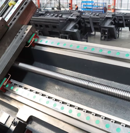
HORISTAR 12-Station Turret Lathe Field Record: TCK63Y Bed-Twist Correction
In June 2026, HORISTAR’s CNC Application Team commissioned a TCK63Y slant-bed turn-mill CNC lathe for an anonymized precision-parts customer in Southeast Asia. The machine had a 10-inch hydraulic through-hole chuck, an 80 mm spindle bore and a 12-station live-tool turret. This is a project-specific result, not a universal tolerance or performance guarantee.
During this field installation, HORISTAR measured a maximum longitudinal level deviation of 0.10 mm/m before correction and 0.018 mm/m after correction.
After lifting and initial placement, level readings changed as the Z axis moved through its travel. Support reaction near the tailstock was low, and the first anchor-tightening pass introduced light bed twist. A 300 mm steel test bar then showed approximately 0.028 mm diameter difference from one end to the other. The team stopped using CNC compensation because an offset would hide the installation load-path problem rather than correct it.
| Check | Before correction | After correction |
|---|---|---|
| Maximum longitudinal level deviation | 0.10 mm/m | 0.018 mm/m |
| Maximum transverse level deviation | 0.06 mm/m | 0.015 mm/m |
| Longitudinal change after initial/final anchor loading | 0.12 mm/m | ≤0.01 mm/m |
| Maximum difference among headstock, center and tailstock readings | Not stable through travel | ≤0.02 mm/m |
| Diameter difference on the 300 mm test cut | 0.028 mm | 0.008 mm |
The team released the first anchor load, returned the machine to natural support, centered the main moving axes and cleaned every pad contact. A 0.02 mm/m precision machine level was used longitudinally and transversely at the headstock, center and tailstock positions. The screws were adjusted in small increments from the headstock reference and then diagonally across the remaining supports.
After the level stabilized, the anchors were tightened progressively and symmetrically. The team repeated the level readings, checked geometry with a laser system and a 0.001 mm indicator, warmed the spindle and repeated the representative test cut. The release condition was full-travel level stability, post-anchor remeasurement, geometry verification and a warm test cut—not merely a centered bubble.
Source: HORISTAR June 2026 internal project record, verified by Doris Li, CNC Application Engineer, HORISTAR CNC Application Team. The customer identity remains confidential.
Worked Verification: Quantify the Test-Cut Improvement
Use the before-and-after test cut to express the practical reduction in diameter variation:
Improvement (%) = (before difference − after difference) ÷ before difference × 100
Substituting the verified field values:
(0.028 mm − 0.008 mm) ÷ 0.028 mm × 100 = 71.4% reduction.
Buyer decision: accept the installation result only when the measured improvement is supported by the raw headstock and tailstock readings, the warm-up state and the same tool/material setup. The calculation does not create a universal machine-accuracy guarantee; it shows that the correction produced a measurable result on the same 300 mm test method.
Source: HORISTAR June 2026 internal project record, verified by Doris Li, CNC Application Engineer, HORISTAR CNC Application Team.
Do Not Choose This Checklist as a Substitute for Site Engineering
This article is useful for a normal machine installation and supplier run-off. Add a qualified structural or installation engineer when the machine is on a cracked or suspended slab, close to heavy impact equipment, subject to seismic requirements, installed on an isolated foundation, or expected to hold unusually tight geometry over a long axis.
Also separate installation acceptance from:
- Electrical and utility commissioning.
- Guarding and safety validation.
- Cutting-tool and workholding validation.
- Customer-specific accuracy tests.
- Operator training and maintenance handover.
One signed leveling sheet cannot close all of those risks.
RFQ and Procurement Checklist for a CNC Turret Lathe Installation
Send the following with a request for installation, alignment or commissioning support:
- Exact machine model, serial number, configuration, quantity and any MOQ or minimum service quantity.
- Foundation drawing, slab information and site photos.
- Floor plan showing services, joints, traffic and nearby vibration sources.
- Expected materials, workholding, chuck, tailstock and turret configuration.
- Required accuracy, tolerance source and customer acceptance format.
- Required measurement tools, raw files, reports and signed acceptance documents.
- Lead time, target date, travel plan, lifting restrictions and production window.
- Sample or representative test-cut policy, plus any anchor, grout or structural work.
- Warranty scope, exclusions, recheck support and the named acceptance owner.
These details reduce procurement friction. Require the quote to state the RFQ inputs, lead time, sample or test-cut policy, warranty, included documents and buyer-supplied work. The turret repeatability guide adds tooling inputs for the same machine.
Send Your Installation Requirement to HORISTAR
Include the machine model, foundation drawing, target accuracy and the first part that must pass acceptance. The CNC application team will connect your installation plan to a measurable release standard.
Frequently Asked Questions
Does every new lathe need anchor bolts?
Should the machine be leveled before or after anchoring?
Is a laser alignment report enough for acceptance?
Why measure the level at both ends of travel?
Why is a generic anchor torque chart not a release document?
Related HORISTAR Guides
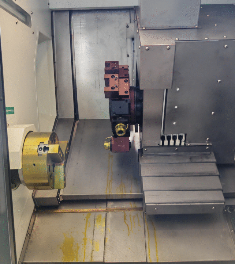
CNC Lathe Pre-Shipment Acceptance Checklist
Configuration, packing and general inspection before the machine leaves the factory.
CNC Lathe Accuracy FAT: ISO 230-2 & ISO 13041 Evidence
The metrology and evidence pack used before the machine ships.
CNC Lathe Turret Repeatability & Surface Finish Tests
Verify servo turret indexing, station layout and cycle time once the machine is running.
Reference data note: Precision-level handling steps and laser-system ranges in this draft are reference values from the linked measurement documents. Confirm all model-specific tolerances, anchor hardware and structural requirements against the released machine manual, approved anchor instructions and site engineer’s design before approval.