Laser Cutting Machine Acceptance Testing: Part Accuracy, Edge Quality and Real Output
A useful laser cutting machine acceptance test proves that the ordered configuration can produce the buyer’s parts under agreed production conditions. It connects three things: the drawing, the cutting process and a traceable result.
Define the acceptance criteria before the demonstration. Then test dimensions, edge condition and complete-job output on representative material. A supplier’s selected sample is useful for discussion, but it cannot establish performance across an untested production range.
The plan below is a practical framework for agreeing and recording a test. The drawing, purchase specification and applicable test methods supply the actual limits.
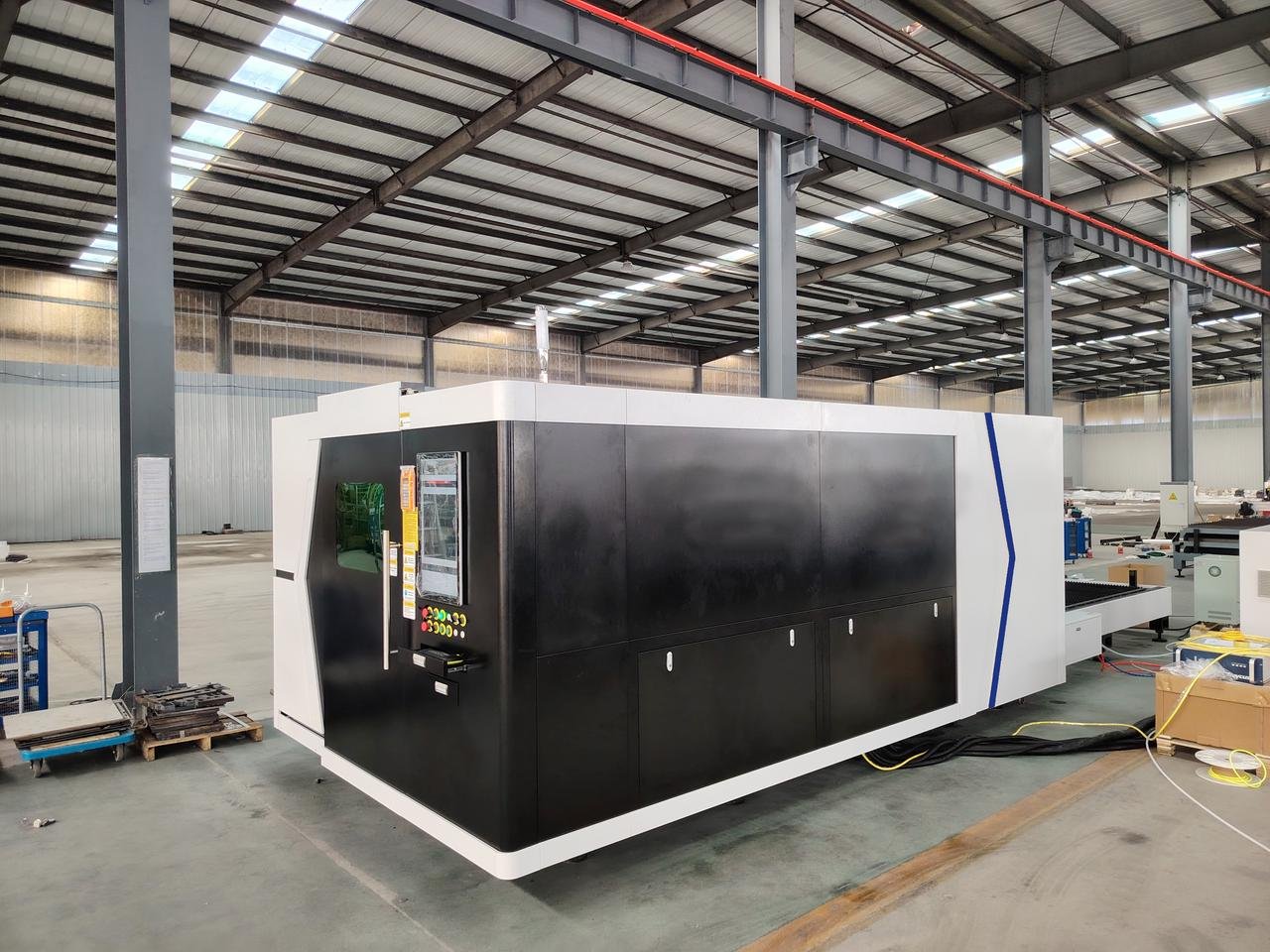
Separate machine positioning from finished-part accuracy
A machine’s axis-positioning figure describes a different measurement from the dimensions of a cut component. ISO 230-2, for example, addresses positioning accuracy and repeatability through direct measurement of individual numerically controlled axes.
A finished part adds the effects of the cutting process, programmed geometry, material condition and inspection method. Ask for both forms of evidence when both are specified:
| Evidence | What it answers | What it does not establish alone |
|---|---|---|
| Axis-positioning test | Does the measured machine axis meet the specified positioning requirement? | Whether the customer’s cut hole or profile meets its drawing |
| Cut-part dimensional report | Did the tested components meet the specified features and tolerances? | Long-term capability across all materials, thicknesses and production conditions |
| Edge-quality inspection | Does the cut surface meet the agreed edge requirement? | Dimensional acceptance or complete production output |
| Timed production run | What acceptable output was achieved under the recorded conditions? | Output under a different nest, material or staffing arrangement |
This distinction prevents a catalogue repeatability number from being copied into a finished-part tolerance without a relevant trial.
A buyer also needs to distinguish three decisions. A factory acceptance test, often called FAT, checks the ordered configuration before shipment. Agreed site acceptance tests, or SAT, check relevant performance after installation. A production capability study examines sustained behavior under a defined production and measurement system. The evidence needed for one does not automatically complete the others.
State the intended decision in the protocol. “Accept this shipment against the agreed test matrix” is a different claim from “demonstrate an ongoing capability index for every thickness in the catalogue.”
Add contouring evidence when the parts depend on it
ISO 230-4:2022 addresses contouring performance through circular tests involving coordinated axes. That asks a different question from independent axis-positioning tests. An appropriate circular test, for example using a suitable ballbar setup, can help investigate errors that appear during coordinated motion and reversals.
Agree the measured characteristic, radius, feed rate, directions, machine location, warm-up and measurement uncertainty. Equipment constraints may prevent reproducing a tiny cut-hole radius directly; state that limitation and retain actual small-hole cut tests. A large-radius, low-speed test does not establish behavior at every smaller radius and production feed.
A good circular test alongside an oval cut hole justifies investigating cutting conditions and measurement, but does not eliminate axis behavior under different conditions. Preserve both records and compare their operating conditions before assigning the cause.
Freeze a test matrix that represents the workload
Choose materials, thicknesses and geometries from real orders. Cover the routine workload and the consequential boundaries: a difficult small feature, a long dimension, a visible edge, or the thickest material that is genuinely part of the purchase specification.
Do not add unrelated materials simply to increase the number of samples. Conversely, a successful carbon-steel trial does not settle an untested stainless-steel requirement.
Use one row for each agreed test condition:
| Test ID | Material and thickness | Drawing and revision | Critical features | Gas and process settings | Sampling locations and repeats | Acceptance reference |
|---|---|---|---|---|---|---|
| — | — | — | — | — | — | — |
For example, the following illustrative buyer workload creates three different testing tasks. The materials and thicknesses are planning examples, not claims about a particular machine’s supplied capability or universal tolerances.
| Example test | Representative part | Features that drive the test | Evidence to retain |
|---|---|---|---|
| T1 | 2 mm 304 stainless enclosure panel | Visible edge, repeated small features, finish orientation and final flatness | Marked drawing, feature measurements, edge record and free-state flatness result using the specified method |
| T2 | 6 mm S235 steel mounting bracket | Mating slot width, hole location relative to datums and cut-face taper | Individual slot/position results; agreed top/bottom or profile measurements |
| T3 | 12 mm S355 steel base component | Long dimension, edge requirement and completion of the nest | Dimensional report at controlled temperature, edge measurements and timed accepted output |
Specify limits from the actual drawing or purchase agreement for each row. A finish-oriented T1 result cannot substitute for T3 edge evidence. A small coupon may isolate a process setting, but it cannot reproduce the support and released shape of a full enclosure panel.
Record the machine configuration and the software or program revision separately. Include the laser source, cutting head, work area, installed options and any auxiliary equipment material to the test.
For each row, agree which parameters are fixed and which the supplier may optimize before the acceptance run. Save the final recipe. If settings change during the measured run, mark the point of change and identify which results belong to each configuration.
Complete the process record with material grade and lot, actual thickness where relevant, assist-gas type and supply conditions, nozzle and focus settings, cutting and piercing recipe, kerf compensation, support condition and the final NC program revision. Record cooling and extraction conditions when they affect the agreed test. These details make a failed repeat test diagnosable.
Separate setup pieces from scored acceptance pieces. Allow documented optimization before freezing the run; then include every scheduled sample and interruption in the scored record. If the process is adjusted halfway through, close that run and identify the subsequent results as a new revision instead of combining favorable pieces from both.
The fiber-laser power and thickness guide can support the earlier sizing discussion. Acceptance should then test the selected configuration against the defined workload.
Define how every critical feature will be measured
Number the features on the drawing or a marked inspection copy. For each, record the nominal value, tolerance, datum reference, instrument and measurement method.
A measurement label such as “hole size” is incomplete if the buyer requires both diameter and location. Similarly, a long slot may need width, length and position checks.
For a hole pattern, preserve the drawing’s datum system and separately report feature size and position. Fitting all holes to an unconstrained best-fit alignment can reduce displayed location errors while removing the datum relationship the assembly actually needs. State the alignment and fitting method used in the report.
A hand caliper reading across a hole does not, by itself, establish its roundness or location. A top-face measurement may also miss a narrower opening below it. Select a method that measures the required feature and define where on the cut surface it applies; avoid replacing a difficult requirement with an easier measurement bearing a similar name.
| Feature ID | Requirement | Method and datum | Sample ID/location | Result | Measurement uncertainty or method limitation | Decision |
|---|---|---|---|---|---|---|
| — | — | — | — | — | — | — |
Select an instrument and setup capable of resolving the required feature. Use the agreed datum alignment rather than choosing an edge that makes the result look favorable. Where edge taper matters, define the measurement plane or top/bottom checks instead of reporting a single unexplained dimension.
Record the condition of the component when measured: as-cut or subsequently finished, cleaned or uncleaned, supported or free, and at what temperature condition. Do not compare a warm as-cut part with a cooled and reworked sample without disclosing the difference.
Establish whether the measurement method can distinguish a real change
Instrument calibration is necessary evidence where applicable, but it does not characterize the entire use of that instrument on a tapered, flexible or rough-edged part. NIST’s gauge R&R guidance addresses repeatability, reproducibility, stability and biases involving resolution, drift and geometry.
Before interpreting a borderline feature, check the following sources separately:
| Contribution | Useful verification | A common mistaken conclusion |
|---|---|---|
| Instrument indication and calibration | Confirm range, calibration status and a suitable reference check | More decimal places mean lower measurement uncertainty. |
| Repositioning and contact | Remove and remeasure the same part using the stated setup | Reading the unchanged display repeatedly proves the whole method is repeatable. |
| Operator or alignment choice | Have another qualified operator apply the same written datum method | Agreement obtained only after both operators choose a favorable alignment proves conformity. |
| Edge geometry and support | Define top/bottom location, contact method and free or supported state | A single width reading represents taper, flatness and mating behavior. |
| Temperature and time | Compare under controlled conditions and retain the temperature record | A cooled result can be compared directly with a warm result without correction or uncertainty. |
These checks help distinguish measurement disagreement from a change in the part. A formal uncertainty evaluation must still address the actual result and configuration; NIST’s uncertainty approach distinguishes those from a general description of instrument precision.
NIST’s work on thermal effects in dimensional measurement explains why temperature contributes to uncertainty. Its dimensional calibration guidance also makes clear that a reported measurement is an estimate with uncertainty.
For scale, use the linear expansion relationship change in length ≈ coefficient × length × temperature change. In an illustrative steel-part calculation, assume a coefficient of 11.5 × 10⁻⁶/°C, a 1,000 mm length and a uniform temperature 8°C above the reporting reference:
Estimated expansion = 0.0000115 × 1,000 × 8 = 0.092 mm.
That is close to the 0.10 mm half-tolerance of a hypothetical ±0.10 mm requirement. NIST’s metrology FAQ uses this coefficient for steel gauge-block examples and explains the uncertainty associated with it. The actual part needs an appropriate material coefficient, temperature information and measurement model; the example does not establish the coefficient of every steel grade.
Record whether the measuring system has already applied thermal compensation, including its reference temperature and material setting. Applying a second correction would introduce an error. A nonuniform warm part also cannot necessarily be described by one temperature and one simple length correction.
Agree a decision rule for borderline measurements
The following is an illustrative decision rule, not a universal acceptance standard: accept a dimension only when its measured interval, including the stated expanded uncertainty, lies wholly within the drawing limits.
Assume a dimension of 40.00 ± 0.10 mm, giving limits of 39.90–40.10 mm. Assume the report states expanded uncertainty of ±0.02 mm and identifies its coverage factor.
| Illustrative measured result | Interval including stated uncertainty | Decision under this agreed example rule |
|---|---|---|
| 40.04 mm | 40.02–40.06 mm | Inside the limits; acceptable for this feature. |
| 40.09 mm | 40.07–40.11 mm | Overlaps the upper limit; conformity is not established by this measurement. |
The second result is not proof that the true dimension is outside tolerance. It needs the agreed disposition: a more capable measurement, process correction and retest, or another documented resolution.
Agree the decision rule and uncertainty treatment before testing. A display with more decimal places does not, by itself, establish measurement capability.
The reporting distinction matters: “not accepted under the agreed rule” and “proved physically outside tolerance” are not equivalent statements. Define whether a borderline result is a contractual failure or goes into a documented hold-and-resolution category.
ILAC G8:09/2019 explains simple acceptance, guard bands and binary or non-binary conformity decisions. A guard band narrows the acceptance interval to address decision risk; it does not change the drawing tolerance. Its size and the treatment of overlapping results must be agreed for the application. Where the specified method already supplies a decision rule, apply that rule rather than adding an arbitrary extra margin.
For the example above, a 0.02 mm guard band at each tolerance limit would leave measured values from 39.92 to 40.08 mm inside the acceptance interval, subject to the agreed boundary convention. Retain the measured result, expanded uncertainty, coverage factor, rule and disposition together. A bare green “PASS” cell loses the information needed to resolve a later disagreement.
For GPS dimensional conformity, ISO 14253-1:2017 addresses decision rules that account for measurement uncertainty. Its published foreword explains that the 2017 revision replaced the earlier default coverage-factor approach with a default conformance probability of 95%.
Do not label the example’s “measured value ± expanded uncertainty inside the limits” rule as an exact statement of that edition’s default. The probability model, applicable rule and any contractually agreed alternative need to be identified. The example illustrates a chosen guard band; it does not reproduce all ISO conformity and nonconformity clauses. Record how borderline results will be resolved before either party makes a conformity claim.
Inspect the edge against a defined requirement
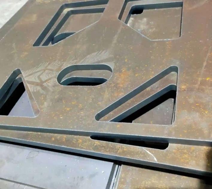
Specify what the next operation needs. An edge going into welding, powder coating or visible assembly can have different acceptance requirements.
Record the relevant characteristics, such as:
- Roughness or cut-face texture, using the specified measurement method.
- Perpendicularity or angularity of the cut face.
- Adhering dross or burrs.
- Piercing and lead-in marks on finished boundaries.
- Complete separation of the required contours.
- Any specified downstream requirement for the edge.
ISO 9013:2017 provides a classification framework for thermal cuts. Its stated scope includes laser cuts from 0.5 mm to 32 mm, and its geometrical specifications apply when referenced in drawings or relevant delivery documents. ISO also lists a 2024 amendment. Identify the agreed edition, amendment and required characteristics when using it.
Do not substitute an arbitrary roughness number or a blanket “ISO compliant” statement for the actual acceptance requirement. The public standard summary also states that flatness defects are not addressed as such; specify any necessary flatness evaluation separately.
Photographs help locate and communicate defects, but they do not replace a specified dimensional or surface measurement. Keep an as-cut sample record before deburring or polishing. If finishing is included in the offered process, record its time and inspect both the as-cut and finished conditions as agreed.
The guide to laser-cut edge preparation before coating is relevant when the acceptance requirement extends beyond cutting.
If the purchase relies on a particular edge-quality class, obtain and use the applicable standard’s measurement details, including the required evaluation locations and treatment of local irregularities. The public ISO scope is sufficient to identify the standard’s purpose; it does not supply all its measurement clauses or numerical class limits.
For a downstream assembly or coating requirement, define the actual functional check separately. A visually smooth edge does not establish coating adhesion, fit or weld preparation. Conversely, an edge requiring an agreed finishing operation should be evaluated with that operation’s cost and output included.
Convert the agreed edge requirement into a measurement decision
Before the run, enter the actual numerical limit at each specified thickness, the characteristic, evaluation location, method and decision rule in the test matrix. If an ISO 9013 range is specified, take its limits and designation from the agreed standard and amendment. Do not assign a range number from an unattributed internet table or assume a general roughness reading is the required profile characteristic.
The following buyer-defined example shows the decision without claiming an ISO quality class. Suppose the agreement for a 6 mm test part specifies a perpendicularity/angularity characteristic with an upper limit of 0.20 mm, and defines its evaluation method. Suppose the selected one-sided guard-band rule accepts only when measured value plus stated expanded uncertainty is at or below that upper limit.
| Measured characteristic | Assumed expanded uncertainty | Upper endpoint | Result under the illustrative rule |
|---|---|---|---|
| 0.18 mm | 0.03 mm | 0.21 mm | Conformity not established. |
| 0.18 mm | 0.01 mm | 0.19 mm | Conformity established for this characteristic. |
The limit and uncertainties are teaching assumptions, not ISO 9013 range values or proposed universal equipment tolerances. The comparison shows why choosing a measurement method is part of specifying acceptance. A smaller reported uncertainty is valid only if supported by the actual method; changing the number on the report is not an improvement.
For a specified roughness characteristic, name the parameter, units, measurement direction, evaluation length, instrument settings and surface locations required by the method. A photograph, a visual comparator and a numerical profile measurement do not establish the same result. Likewise, accept or reject a square-and-gauge method according to its demonstrated capability for the required characteristic, rather than declaring it suitable or unsuitable from the nominal tolerance alone.
Sample across location and operating time
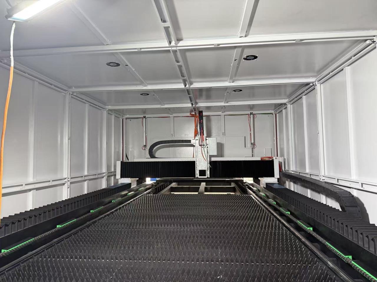
Choose the sample count and locations with the supplier according to the importance of the features and the intended workload. Identify samples so the report can distinguish:
- Different areas of the worktable.
- Early and later parts in the agreed run.
- Repeated identical features.
- Relevant material or thickness conditions.
- Any restart or adjustment.
Keep a nominal baseline. If a later part differs, first check that material, program, inspection method and measurement condition are comparable. Then investigate the pattern rather than averaging the difference away.
A failure across many locations may call for a different investigation from a failure confined to one geometry or one region. A pass on one test condition should remain attached to that condition; it does not erase a failed result elsewhere.
A limited acceptance run demonstrates the tested conditions. Establishing ongoing statistical process capability requires an appropriate sampling and analysis plan beyond a few favorable parts.
Use a coverage plan without calling it proof of long-term capability
For one material/process condition, an illustrative exploratory plan could inspect identical features in three bed zones, at two points in the run, across three repeated runs: 18 specimens in total. Give them IDs that encode run, location and sequence. This helps separate location, operating-time and repeat-run patterns.
It is not a universal acceptance sample size. Additional materials, loading conditions or critical geometries require their own coverage. Consequences of failure and the buyer’s quality requirements determine the formal plan.
Even a perfect small sample has limited evidential strength. If a hypothetical stable process independently rejects 5% of parts, the chance of observing zero rejects in 20 random parts is 0.95^20 ≈ 35.8%. That calculation is conditional on the assumed process; it is not a 35.8% probability that an actual tested machine is defective. It shows why a short run with no failures cannot establish a very low future defect rate.
Plan a zero-failure demonstration before producing the sample
For an illustrative binomial model, assume independent parts, a stable defect probability, a representative preselected sampling plan and effective inspection against fixed criteria. A planned sample with zero failures has a one-sided upper confidence bound:
p_upper = 1 − (1 − C)^(1/n),
where C is the confidence level and n is the number inspected. To make that bound no greater than a target defect probability p, choose:
n ≥ ln(1 − C) ÷ ln(1 − p), rounded up.
| Target upper defect probability | Confidence level | Required planned sample, with zero failures | Probability of zero failures if the true rate equals the target |
|---|---|---|---|
| 5% | 95% | 59 parts | 0.95^59 ≈ 4.85% |
| 1% | 95% | 299 parts | 0.99^299 ≈ 4.95% |
The unrounded sample calculations are about 58.404 and 298.073. The shortcut n ≈ 3 ÷ p is an approximation at 95% confidence, not a separate acceptance standard.
This is a fixed-sample plan, not permission to keep testing until 59 favorable consecutive parts appear. Choose the sample size in advance and retain every scheduled result. A failure invalidates the zero-failure claim for that run; apply the agreed disposition or a different preplanned analysis. Process changes require a separately identified run, not selective deletion of the earlier results.
The confidence statement concerns this model and sampling procedure. It is not a 95% probability that a particular machine’s unknown defect rate lies below the target. Correlated defects, drifting conditions, unrepresentative sampling or missed defects undermine the inference. A coverage trial across very different materials is not automatically one population with a single common defect rate.
Interpret capability indices only after checking their assumptions
NIST defines process capability by comparing a stable process distribution with specification limits. For the usual normal-distribution model:
Cp = (upper limit − lower limit) ÷ (6 × standard deviation)describes spread relative to tolerance width.Cpktakes the smaller distance from the mean to either limit, divided by three standard deviations, so it also reflects centering.
In an illustrative calculation, use limits 39.90–40.10 mm, mean 40.06 mm and estimated standard deviation 0.02 mm. Then Cp = 0.20 ÷ 0.12 ≈ 1.67, but Cpk = 0.04 ÷ 0.06 ≈ 0.67. The tighter distance to the upper limit makes the centering problem visible despite the apparently favorable spread.
These calculations do not establish an acceptance threshold. They require an adequate, representative study, a capable measurement method and appropriate distribution assumptions. NIST’s stability guidance emphasizes examining behavior over time before making capability claims. Do not pool different thicknesses or corrected and uncorrected runs into one convenient index.
Measure output from the complete job
Agree the beginning and end of the timed interval. Include the activities relevant to the buyer’s required output: loading, cutting, interruptions, unloading and any finishing or inspection included in that output definition.
For a sequential trial, consider this illustrative example:
| Activity | Assumed elapsed time |
|---|---|
| Loading and setup for the measured batch | 12 minutes |
| Machine cutting, including recorded interruptions | 45 minutes |
| Unloading and sorting | 10 minutes |
| Required inspection | 8 minutes |
| Total sequential time | 75 minutes |
Assume 100 parts are produced and 96 pass the agreed inspection.
Accepted output = 96 × 60 ÷ 75 = 76.8 acceptable parts per hour.
Counting all 100 parts over cutting time alone would describe a different metric. Neither number should be presented without its time boundary and acceptance definition.
If operations overlap, use the measured elapsed interval rather than adding overlapping durations. Record operator attendance separately. If rejected parts need replacement to finish the order, add the replacement production to the order-completion estimate.
Also log the cause and duration of stops. A timing result is more useful when the buyer can see whether delays came from cutting, part removal, material handling or an adjustment.
Agree who performs each operation during timing. Record whether the supplier’s specialist, the buyer’s trained operator or an automatic system removes, sorts and inspects the parts. Include work shifted to an external station when it is necessary to reach the defined output condition. A faster cutting cycle that creates a queue for tab removal has shifted the constraint rather than necessarily improved completed-job output.
Decide what happens when a result fails
Use a result register that preserves both the original finding and the response:
| Test/feature | Agreed criterion | Observed result | Disposition | Corrective action and revision | Retest evidence | Final status |
|---|---|---|---|---|---|---|
| — | — | — | — | — | — | — |
Resolve failures in a controlled sequence:
- Confirm the drawing, sample identity and measurement method.
- Identify whether the evidence points to measurement, material, programming or the cutting process.
- Document the correction and any configuration change.
- Repeat the failed condition and relevant baseline checks.
- Record whether the result now meets the agreed criterion.
If a correction could affect neighboring features or another material condition, extend the retest accordingly. Do not delete the first failure or silently widen the tolerance.
Use the error pattern to choose that retest:
| Observed pattern | Investigation that separates possible causes | Retest that closes the question |
|---|---|---|
| Hole size passes, hole position fails | Review datum alignment, feature fitting, program geometry and independent position measurement | Repeat the same datum-based positional check; another diameter reading is insufficient. |
| Outside profiles and internal openings show opposing size errors | Review kerf compensation and compare raw path geometry with measured top/bottom edges | Recut both internal and external reference features using the documented correction. |
| Dimensions change with bed location | Repeat identical geometry with comparable stock and measurement conditions; review axis evidence if required | Repeat the affected and reference zones, preserving their locations. |
| Long dimensions shift with temperature | Confirm part temperature, reporting reference and existing compensation | Remeasure or recut under the controlled method; do not simply offset the program to match a warm sample. |
| Geometry passes, downstream fit or edge condition fails | Confirm that the drawing checks captured the functional requirement and that finishing is included | Repeat the agreed functional or edge test as well as dimensions potentially affected by the correction. |
These patterns guide investigation; they do not prove a unique machine fault. For example, opposite internal/external errors make compensation worth checking, but the measurement plane or process taper may also be involved.
Record utilities and safety verification as separate acceptance items
For each scored run, record assist-gas type, supply pressure at the machine under flow, and purity where the approved recipe specifies it. Retain chiller settings and relevant cooling and extraction conditions. A static supply-pressure reading may not describe delivery during a long cut; a factory gas supply does not establish the behavior of a different site supply.
ISO 11553-1:2020 addresses laser-radiation hazards and related safety requirements for laser processing machines, including manufacturer information. Agree the applicable handover documents and checks for the installed enclosure, interlocks and warnings with qualified personnel. Conduct them under the supplier’s approved procedure and record their results separately from cutting-quality measurements.
That standard’s scope is not a complete list of all machinery hazards or destination requirements. The handover must cover the applicable installed system. A passing dimensional report does not establish safe guarding, and a completed safety check does not establish part accuracy.
Build a handover package that can be repeated after installation
Keep the final test matrix, drawings, programs, process settings, sample identities, measurement results, timing records and outstanding-item register together. Add instrument identification and calibration information relevant to the reported measurements.
After transport and installation, repeat the agreed site checks using the same reference parts and method where practical. Record differences in utilities, setup or environment rather than assuming the factory trial covers changed conditions.
Use a transfer checklist for anything that could break comparability: machine leveling and support, gas supply under operation, cooling settings, extraction, program and compensation data, material condition, measuring method and trained staffing. Define beforehand which FAT tests will be repeated at site and which evidence remains valid without repetition.
If the site result differs, first reproduce a common reference condition. A comparison using a new stock batch, a changed nest and a different gauge simultaneously cannot isolate transport or installation as the cause. Preserve both records, then change the suspected variable under a controlled retest.
For a HORISTAR laser cutting machine enquiry, send representative drawings with marked critical features, the material range, required edge condition and target acceptable output. Ask to agree the test matrix and evidence package with the quotation.
This turns the demonstration into a purchasing record that both sides can interpret: what was tested, under which conditions, what passed and what still needs resolution.