Digital Knife Cutting for Acoustic Insulation and Honeycomb Composites
By HORISTAR · Updated September 23, 2026
Acoustic insulation and honeycomb composites should be specified by their layer structure, not just by the word “foam” or “composite.” The right digital knife setup depends on the facing, core, adhesive, thickness, density, allowable compression and the smallest feature in the drawing.
The useful starting point is a sample workflow: identify the stack, choose a tool family, hold the sheet without crushing it, then test the cut order and edge quality on the actual material. A large cutting table or a high advertised speed cannot compensate for the wrong blade, a leaking vacuum zone or a toolpath that lets a flexible layer move.
Key takeaways
- “Composite” is not one material. Record the core, skins, adhesive, cell direction, thickness and density before choosing the knife.
- Zünd’s published tool examples include 0.5/1 mm, 2.5 mm and 8 mm oscillating strokes for different material classes; these are vendor-specific tool examples, not HORISTAR settings.
- A paper or aramid honeycomb core, an aluminum honeycomb panel and a cured fiber-reinforced skin can require different tools or a different process.
- Accept a setup only after measuring the cut coupon immediately and after the material has recovered from cutting-table compression.
Quick tool direction
| Material or job condition | Tool direction to evaluate | Main risk to test |
|---|---|---|
| Soft felt, thin foam or flexible facing | Drag knife or a small-stroke oscillating knife | Pulling, lifting, compression and ragged corners |
| Thick or tough foam and rubber-like layers | Larger-stroke oscillating knife | Heat, tearing, blade deflection and incomplete bottom cuts |
| Bare honeycomb core or a documented trial stack | Oscillating blade with controlled depth and a stable underlay | Crushing cells, delamination and skin breakout |
| Large radii or porous sheet | Rotary blade may be worth a trial | Edge compression, drag and dimensional growth |
| Small holes, tight inside corners and short contours | Pointed blade or a fine tool selected for the material | Corner overcut, snagging and tool marks |
| Large parts with long straight edges | Flat-tipped blade or another stable cutting edge | Wandering, local lift and loss of squareness |
This is a test plan, not a universal tool chart. Tool stroke, blade angle, depth, speed and oscillation frequency must be matched to the machine and material.
Define the material boundary
| Material family | What to record first | First decision boundary |
|---|---|---|
| Acoustic felt or textile | Fibre direction, thickness, compression and edge fray | A drag or small-stroke trial may be reasonable if the sheet stays flat |
| Open-cell or closed-cell foam | Density, rebound, skin/film and adhesive | Test compression and recovery; nominal thickness alone is not enough |
| Paper or aramid honeycomb core | Cell size, cell direction, resin condition and exposed edge | A knife trial can be relevant for the core; protect cells from vacuum and blade pressure |
| Aluminium honeycomb or metal-faced sandwich | Skin thickness, bond line, edge closure and burr/particle requirement | Do not assume a soft-material knife process will cut the finished panel; require a machine-specific trial or alternate process |
| Cured CFRP/GFRP or rigid mineral-filled skin | Fibre orientation, dust, delamination risk and required edge/seal | Treat the rigid skin as a separate process decision; routing, scoring or another controlled process may be more appropriate |
This boundary prevents the product-page term “composites” from becoming an unsupported capability claim for every composite construction.
Material class changes the process hypothesis. Acoustic felt and open-cell foam are compressible and porous, so test whether vacuum flattening changes thickness and whether a small-stroke oscillating tool or drag knife leaves a stable edge. Closed-cell foam may spring back and can hold less uniformly at the seal; measure thickness and dimensions after release. Bare paper or aramid honeycomb is a cellular core, not a faced sandwich; record cell direction and inspect cell crush. Aluminum honeycomb is specified by alloy, cell size, foil thickness and density, so do not transfer a paper-core setting. A cured CFRP sandwich combines a structural skin, adhesive and core; a digital knife trial must prove that the skin is cut without fiber pull-out or delamination, and routing or another process may be the appropriate route. These are test hypotheses, not a guarantee that one HORISTAR tool or setting supports every stack.
The Hexcel honeycomb attributes reference separates cell size, alloy, foil, density, stabilization and facing conditions. Use those fields in the material record instead of sending “honeycomb panel” as the whole specification. A bare core, a stabilized core and a cured sandwich can require different support and cutting decisions.
Scope and evidence
The Zünd and Hexcel documents below are public tool and material references. They do not prove that a Zünd tool, a Hexcel machining route or a particular cutting setting is installed on or validated for a HORISTAR machine. HORISTAR capability should be accepted from a current configuration sheet and a representative sample test.
1. Record the material stack before choosing a tool
Send the supplier a cross-section, not only the top-view drawing. Record:
- overall thickness and the tolerance of each layer;
- core type, density and cell size;
- facing or film on each side;
- adhesive, scrim, foil, paper or textile reinforcement;
- whether the material rebounds after compression;
- whether dust, loose fibers or adhesive residue are acceptable;
- the smallest hole, inside radius and narrowest web in the part;
- the number of layers or panels cut in a shift.
Two sheets with the same thickness can behave very differently. A soft open-cell foam may close around the blade, while a dense elastomer may resist the cut and pull the sheet. A honeycomb panel may have a light core but a fragile skin that determines the tool and cutting direction.
HORISTAR’s digital knife machine page positions oscillating-knife systems for foam, composites, packaging and other flexible or semi-rigid materials. That broad capability is useful for starting a discussion; it does not establish that every layer stack can be cut with one blade or one setting.
For adjacent use cases, compare the gasket cutting application and the packaging-sample workflow. They are useful references, but neither one proves that an acoustic or honeycomb stack has the same tool window.
The product page also presents an accuracy figure of up to 0.1 mm. Treat that as a published product-page claim, not as the expected tolerance for an untested acoustic or honeycomb stack. Record the actual stack, tool, offset, hold-down and measurement method before repeating the figure in a quotation.
2. Match the tool to the failure you need to avoid
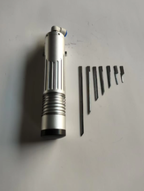
Oscillating knife for thickness and toughness
An oscillating blade moves through the material rather than relying only on drag. It is a natural first trial for thicker, tough or layered materials. A smaller stroke can be easier to control in soft and medium-density materials; a larger stroke can help when the material resists the cut.
The blade still has to be selected for the contour. A pointed tip can reach a small radius, while a flatter cutting edge can be more stable on long straight lines and broad curves. Zünd’s tool guide makes this distinction explicitly: oscillating cutting is suited to thick and tough materials, with pointed blades for smaller radii and flat-tipped blades for larger radii, straight lines and large parts.
The Zünd Modules & Tools guide gives example strokes of 0.5 or 1 mm for soft and medium-density materials, 2.5 mm for a powerful oscillating tool used on tougher material, and 8 mm for dense materials. These numbers describe Zünd tool examples. Use them to ask what stroke range a proposed HORISTAR configuration can control; do not paste them into a HORISTAR parameter sheet.
Drag knife for thin, flexible layers
A drag knife can be efficient on thin films, paper-like facings and flexible materials when the sheet stays flat. It is less forgiving when the core compresses or the facing catches the blade. A drag setup should be tested on corners, slots and the narrowest web rather than only on a long straight cut.
Rotary blade for selected porous materials
A rotary blade can reduce drag on some porous or textile-like materials and can be useful for long cuts and broad radii. It is not automatically better for a sandwich panel. Test the edge for compression and check whether the wheel pulls the facing as it enters a turn.
Router or another process for unsuitable layers
Some rigid skins or bonded panels may need scoring, routing or another controlled process. If a knife leaves delamination, fiber pull-out, edge dust or an unsealed edge after a controlled trial, changing only the feed speed is unlikely to solve the process problem.
3. Use vacuum hold-down as a process control
Vacuum is there to prevent movement during the cut. It is not a licence to compress a soft core until its nominal thickness disappears.
Set up the table in zones so that unused areas do not consume the available vacuum. Use a suitable cutting underlay to protect the table and provide a stable surface. Zünd’s tool documentation describes underlays in its own routing and cutting-tool ecosystem; use that as a hold-down principle, not as a claim that a Zünd accessory is installed on a HORISTAR machine.
Check the following before increasing cutting speed:
- Is the sheet flat before vacuum is applied?
- Does the seal hold around porous or perforated material?
- Are open zones closed so the pump is not pulling air through the whole table?
- Does the underlay support the bottom skin without bridging a void?
- Does the vacuum hold the part after the first internal cut releases a large area?
- Does the vacuum deform the core or leave a visible imprint on the facing?
For a honeycomb panel, the support strategy may need a sacrificial layer or a perimeter seal. Confirm the result by measuring the finished panel after it has recovered from the table.
If vacuum deforms the core, the held shape can differ from the released shape; measure recovered dimensions to check for an error. If the vacuum seal is weak, the sheet moves instead and the edge shows wandering or an incomplete bottom cut. The same symptom can therefore have opposite causes, which is why the hold-down record belongs beside the cut result.
Sample-coupon geometry
Use one coupon that contains at least six features: a long straight edge, a broad radius, the smallest inside radius, a slot, a small hole and a narrow web. Cut an internal feature before the outside perimeter, then repeat the perimeter with the planned nesting direction. Measure the coupon immediately after cutting and again after the material has recovered according to the supplier’s or trial team’s defined interval. This reveals tool wear, vacuum instability, cell crush and recovery separately instead of hiding them in one overall dimension.
4. Plan the cut path for stability
The order of cuts can change the part even when the tool and speed stay constant.
- Cut internal openings while the outer perimeter still holds the sheet.
- Leave small bridges or tabs when a flexible offcut would otherwise lift into the blade.
- Avoid starting a cut on a fragile skin edge if a lead-in can be placed in waste material.
- Keep the last perimeter cut until the internal features are complete.
- Reduce direction changes near small radii and narrow webs.
- Nest parts so the remaining web supports the sheet instead of creating a long loose strip.
- Mark the fiber, face or cell orientation when it changes the part’s acoustic or structural behavior.
For a layered panel, the best path may not be the shortest path. A slightly longer route that keeps the part supported can produce a cleaner edge and fewer manual repairs.
5. Validate the actual stack with a sample matrix
Ask for a sample that represents production, not a single easy rectangle.
| Test item | What to include |
|---|---|
| Material | Each layer, adhesive and facing used in production |
| Thickness | Minimum, routine and maximum stack |
| Geometry | Straight edge, tight radius, slot, small hole and narrow web |
| Tool | Tool name, blade type, stroke, depth and replacement condition |
| Hold-down | Vacuum zone, underlay and observed compression |
| Path | Lead-in, cut order, bridges/tabs and nesting direction |
| Inspection | Edge fray, skin delamination, cell crush, dimensional change and face marks |
| Recovery | Part dimensions after the material has rested and returned toward its uncompressed state |
For acoustic products, add the orientation and face identification to the sample record. A part can be dimensionally correct and still be installed with the wrong face or cell direction.
Troubleshooting by symptom
| Symptom | First checks |
|---|---|
| Edge is ragged on the bottom | Blade depth, underlay, vacuum stability and whether the tool completed the bottom layer |
| Facing lifts at corners | Tool type, corner speed, lead-in and whether the cut order released the support too early |
| Honeycomb cells collapse while the sheet stays fixed | Vacuum compression, support underlay and blade pressure; reduce compression only while maintaining secure hold-down |
| Part moves after an internal cut releases support | Vacuum zoning, seal loss, underlay contact and the cut order; rerun the same path with a fresh blade |
| Long straight cut wanders | Sheet tension, vacuum zoning, blade deflection and nesting orientation |
| Small holes are oversized | Blade tip, offset compensation, tool wear and material rebound |
| Adhesive smears the edge | Blade cleanliness, heat from excessive rubbing and the correct tool for the adhesive layer |
| Part changes size after cutting | Core recovery, facing tension, temperature and when the measurement was taken |
Do not solve every defect by increasing speed. A faster cut can increase drag, vibration or layer movement. Change one variable at a time and record the actual edge and dimensional result.
What to include in a quotation request
Send the supplier:
- a cross-section and the material supplier’s datasheet;
- thickness, density and layer tolerances;
- CAD files plus the smallest feature and narrowest web;
- daily sheet size, nesting pattern and expected cycle volume;
- the acceptable edge condition and any secondary sealing or bonding step;
- whether the face, cell direction or fiber direction must be preserved;
- the vacuum table requirements and available floor space;
- sample parts or offcuts for a cutting trial.
Ask for a tool list and a sample-test report. The report should identify the tool, vacuum zone, underlay, cut order and inspection timing so the result can be repeated after installation.
Frequently asked questions
Why can more vacuum create a dimensional error?
A porous or compressible stack can deform while it is held. If the tool cuts the compressed shape, the part can change size after release. Measure both the held state and the recovered state, then set the hold-down from the drawing tolerance rather than from maximum pump capacity.
Why cut internal holes before the outside profile?
The uncut perimeter keeps the sheet supported. If the outside is released first, a flexible offcut can lift, rotate or pull the blade as the remaining holes are cut.
How do I separate blade wear from vacuum instability?
Repeat the same coupon after cleaning or replacing the blade while keeping the vacuum record unchanged. If the defect follows blade condition, inspect edge wear and offset. If it follows the open zone, material seal or underlay, inspect the hold-down before changing the toolpath.
Can the published 0.1 mm accuracy be used for honeycomb panels?
Not without a stack-specific trial. The product page’s “up to 0.1 mm” statement is a published capability claim; it does not establish the tolerance of a particular core, skin, adhesive, blade, vacuum condition or recovery state.
Final recommendation
Treat a HORISTAR digital knife as a candidate process for the listed flexible or semi-rigid materials and an approved stack, not as a blanket guarantee for all acoustic products, honeycomb cores or cured composite panels. Choose the tool, depth, vacuum, underlay and cut path together, then accept the configuration only after a representative stack is cut and measured. The most useful proof is a repeatable sample record that shows a stable edge, intact layers, controlled compression and dimensions after recovery.
Sources
- HORISTAR Digital Knife Cutting Machine — current product scope for foam, composites and other flexible or non-metal materials.
- HORISTAR Digital Knife Cutting Machine for Packaging Samples — related short-run digital-cutting workflow and sample-cut context.
- Zünd Modules & Tools PDF — tool-selection guidance for oscillating blades, drag knives, rotary blades, composites, foams, honeycomb materials and cutting underlays.
- Zünd Modules and Tools — current manufacturer overview for module and tool families.
- Hexcel Honeycomb Attributes and Properties — material fields such as cell size, alloy, foil and density.
- Hexcel HexWeb Engineered Core — distinctions among bare, stabilized and faced/engineered core constructions.