Fiber Laser Assist Gas and Nozzle Selection Guide
By HORISTAR · Updated September 23, 2026
The right assist gas and nozzle setup is part of the cutting process, not an accessory to be chosen after the laser power. Gas removes molten material from the kerf, while the nozzle turns the supply pressure into a controlled jet. A poor combination can leave dross, discolor the edge, destabilize piercing, or consume more gas without improving the part.
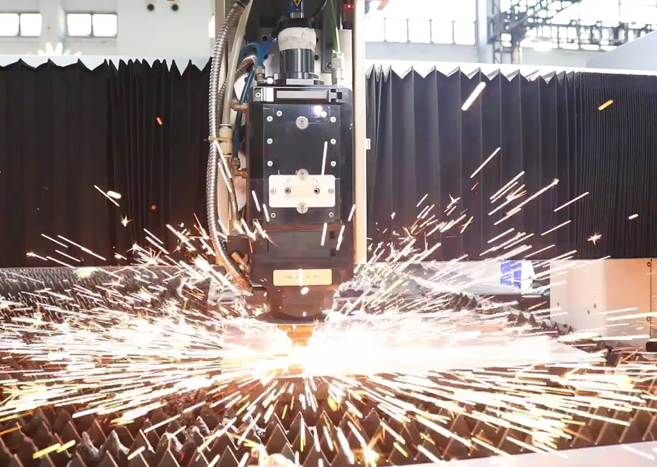
The practical decision is simple: start with the material and the finished-edge requirement, then confirm the gas, nozzle, stand-off, pressure and cutting speed on the machine that will produce the parts. A published gas chart is a starting window. It is not a substitute for a sample cut.
Key takeaways
- Oxygen, nitrogen and compressed air solve different edge and cost problems; none is a universal default.
- Nozzle diameter, concentricity and stand-off control how much of the gas jet reaches the kerf. A damaged nozzle can invalidate an otherwise correct parameter set.
- HORISTAR’s current power guide uses 3, 6, 12 and 20 kW as reference power bands, but power does not replace gas and nozzle validation.
- Accept a configuration only after recording material, thickness, gas, nozzle, stand-off, pressure, edge condition and downstream cleaning or welding results.
Quick decision guide
| Production need | First gas direction to evaluate | What must be confirmed |
|---|---|---|
| Carbon-steel parts where an oxidized edge is acceptable or will be cleaned and coated | Oxygen-assisted cutting may be the first trial | Edge oxide, dross, downstream coating or welding requirements, and the oxygen setting in the machine chart |
| Stainless steel or aluminum where a clean, low-oxidation edge matters | Nitrogen or another approved inert-gas route is usually the first trial | Gas purity, supply stability, pressure, edge color, dross and operating cost |
| Prototypes or cost-sensitive work where the edge specification is forgiving | Compressed air can be evaluated if the machine maker approves it | Moisture and oil filtration, edge oxidation, dross, cut consistency and the actual cost of rework |
| Thin sheet, small holes or fine contours | Use the nozzle and parameter window intended for the thin-material job | Jet alignment, stand-off, pierce stability and heat input |
| Thick sheet or high-throughput production | Use the machine maker’s thick-material gas and nozzle chart | Pressure capacity, melt removal, pierce time, extraction and continuous runtime |
These are decision directions, not universal settings. Gas behavior changes with the alloy, thickness, laser source, cutting head, focal position, nozzle geometry and the cleanliness of the gas path.
Why assist gas changes the cut
Laser cutting does two jobs at once. The beam supplies heat, and the gas jet helps remove the molten material from the kerf. A review of laser-cutting research describes the gas jet as a major part of melt removal and explains that pressure, gas density, viscosity and jet velocity affect the forces acting inside the cut. The same review notes that nozzle diameter changes both the useful thrust location and gas consumption.
That is why a change in gas or nozzle can alter the result even when the laser power stays the same:
- Reactive gas can add heat. Oxygen can react with suitable materials and contribute heat to the cut. That may support productivity on some carbon-steel work, but it also changes the edge chemistry.
- Inert gas protects the edge. Nitrogen-based cutting is often evaluated when the edge must stay bright and low in oxide, especially before visible finishing or welding. The required purity and pressure are part of the result.
- Air is a process compromise. Air can reduce gas cost, but its moisture, oil contamination and oxygen content can affect edge condition. Use it only when the equipment and the finished-part requirement allow that compromise.
- The nozzle shapes the jet. Diameter, orifice condition, concentricity and stand-off determine how effectively the jet reaches the kerf. A larger opening can increase consumption; a smaller opening can become sensitive to contamination and alignment.
The research evidence does not support copying one nozzle diameter or pressure across every machine. The optimum depends on the material and the rest of the process window.
When gas pressure falls below the stable process window, the jet loses momentum and more melt can remain attached as dross. When moisture or oil enters compressed air, it can change the edge condition and contaminate a downstream weld or coating. These cause-and-effect checks are more useful than treating gas as a line item in the quotation.
A repeatable selection workflow
1. Define the edge before choosing the gas
Write down what the edge must do after cutting:
- Will it be powder-coated, painted, welded or left visible?
- Is a heat-tinted or oxidized edge acceptable?
- Is the customer measuring dross, roughness, burr height or dimensional accuracy?
- Are small holes, narrow slots or long straight edges the difficult features?
If a part will be welded or coated, the gas decision must include the next process. A low cutting cost can disappear if the edge needs extra cleaning or if oxide affects adhesion or weld preparation.
For the downstream consequence, compare the laser-cut edge finishing guide. For the workshop-level safety and extraction decision, use the closed-versus-open fiber laser guide.
2. Separate routine thickness from the occasional maximum
List the thicknesses that run every week, then list the thickest material that is only an occasional job. Size the gas supply and nozzle plan around the routine workload, while checking that the occasional job remains feasible.
HORISTAR’s fiber-laser power guide already treats thickness, throughput, assist-gas cost and piercing time as connected sizing factors. That same logic applies here: do not select gas from the maximum thickness printed in a brochure while ignoring the material mix that drives daily consumption.
Use the HORISTAR fiber-laser power and thickness chart for power sizing, then use this article to define the gas and nozzle evidence that the power chart cannot provide.
Bounded reference points, not universal recipes
| Reference point | What it tells the buyer | Boundary |
|---|---|---|
| 3 / 6 / 12 / 20 kW | HORISTAR power-guide bands for connecting routine thickness with throughput and gas cost | These are sizing references, not a gas or nozzle setting for every machine |
| 2.0–2.5 mm nozzle exit diameter | A published CO2-laser study’s example range for maximising speed on 3 mm aluminum-copper under a defined 2.5 kW argon setup | Do not copy this diameter to another alloy, head, pressure or thickness |
| ISO 9013 | A useful reference when the buyer needs to discuss thermal-cut edge quality | The supplier must state the inspection method and applicable quality class |
The nozzle example comes from a documented CO2-laser experiment, not a fiber-laser parameter recommendation or a HORISTAR production guarantee. The right use of a number is to make the test conditions explicit, not to turn it into a universal setting.
Where edge classification matters, ask whether the supplier will report the applicable ISO 9013 quality class and measurement method. If the machine is enclosed or operated near other staff, ask for the documented laser classification and interlock evidence under the applicable safety framework, including IEC 60825-1 where relevant.
3. Select a gas family, then check the supply path
For the first trial, record the proposed gas, purity requirement, supply pressure, regulator capacity, pipe size and filtration. The machine can only use the gas that arrives at the cutting head. Pressure drop, moisture, oil, leaks and a regulator that cannot recover between pierces can appear as cutting defects.
For nitrogen or another inert-gas route, ask how purity is specified and measured. For compressed air, ask for the filtration and dryer specification. For oxygen, confirm the machine’s approved components and the site’s safety requirements.
4. Choose the nozzle with the machine chart
The nozzle should match the cutting head, material thickness and gas route. Ask the supplier to state:
- nozzle type and orifice diameter;
- recommended stand-off and how it is measured;
- centring procedure and acceptable alignment;
- pressure and flow range at the head;
- single- or double-layer design, if applicable;
- inspection and replacement criteria.
Treat the nozzle as a wear part. A damaged or partially blocked orifice can make a correct parameter set look unstable. Replace or clean it before changing laser power or speed.
5. Validate a small, useful sample matrix
Do not ask for one decorative sample. Ask for the parts that represent production risk:
| Test item | Minimum useful evidence |
|---|---|
| Materials | Every material family in the order scope |
| Thickness | Thin, routine and upper-range thickness |
| Features | Straight edge, small hole, slot and the tightest contour |
| Gas comparison | The recommended gas plus one credible alternative when cost or finish is disputed |
| Nozzle check | The proposed nozzle, stand-off and alignment record |
| Inspection | Edge photographs, dross/oxide observations, dimensional checks and a note on downstream cleaning |
| Runtime | Enough repeated parts to expose pressure recovery, alarm or heat problems |
The conclusion should name the conditions. “Nitrogen was better” is incomplete. State the material, thickness, nozzle, pressure, speed, edge requirement and what was inspected.
Troubleshooting by symptom
| Symptom | Check first | Why it matters |
|---|---|---|
| Dross on the underside | Nozzle centring, stand-off, gas pressure and speed | Melt removal may be unstable; changing power first can hide the cause |
| Dark or colored edge | Gas family, purity, leaks and the downstream requirement | Oxidation may be acceptable for one process and unacceptable for another |
| Piercing breaks through or alarms | Pierce gas, nozzle condition, stand-off and material flatness | A cutting parameter cannot repair an unstable pierce sequence |
| Good result at the center, poor result at the sheet edge | Gas flow, sheet support, nozzle alignment and extraction | The local flow and heat conditions may have changed |
| Gas consumption is unexpectedly high | Nozzle diameter, leaks, regulator recovery and idle flow | A larger or damaged orifice can raise cost without improving the edge |
| Results drift during a shift | Lens/protection-window condition, nozzle contamination, gas supply and temperature | Drift is evidence of a changing process, not proof that the original chart was wrong |
What to send with an RFQ
Give the machine supplier enough information to propose a testable configuration:
- material grades and thickness range;
- routine sheet size and the smallest recurring feature;
- edge finish, coating and welding requirements;
- monthly sheet volume and expected shift pattern;
- available gases and supply method;
- site voltage, extraction constraints and destination-country requirements;
- drawing files for a representative sample;
- the measurements that will decide acceptance.
Ask for the recommended gas, purity, nozzle, stand-off, pressure range and sample-test record in the quotation. That turns “can it cut this?” into a configuration that can be checked after delivery.
A nozzle and gas acceptance record
Copy these fields into the RFQ or sample-test sheet:
| Field | Record |
|---|---|
| Material and grade | Exact grade, coating and thickness |
| Laser configuration | Source power, cutting head and focal setup |
| Gas | Gas family, purity, supply method and filtration |
| Nozzle | Type, exit diameter, condition and centring result |
| Flow conditions | Inlet pressure, cutting pressure, flow if measured, and stand-off |
| Cut evidence | Edge color, dross, roughness, hole quality and piercing stability |
| Downstream result | Cleaning time, weld preparation or coating result |
| Repeatability | At least three representative parts or the buyer’s agreed sample count |
This record creates a useful boundary between a brochure capability and a repeatable production process.
Frequently asked questions
Is nitrogen always better than oxygen for stainless steel?
No. Nitrogen is often the first route to evaluate when a low-oxidation edge matters, but the result still depends on purity, pressure, nozzle alignment, focal position and the machine’s parameter window. Accept it only against the required edge and downstream process.
Why can the same parameter fail near the sheet edge?
The local support, heat flow, gas flow and extraction conditions can change near the edge. Check sheet support, nozzle alignment and gas behavior before changing laser power.
How do I know that a nozzle is damaged?
Look for an obstructed or distorted orifice, loss of centring, unstable piercing and a dross pattern that was absent with a clean nozzle. Replace or clean the nozzle before changing the entire cutting recipe.
How should gas cost be compared?
Compare cost per accepted part, not only price per cylinder or cubic metre. Include gas consumption, pierce losses, cleaning time, scrap and any extra preparation before welding or coating.
Final recommendation
Choose assist gas and nozzle settings as a matched process. Use oxygen, nitrogen or air only in the context of the material and the edge you need; use the machine maker’s nozzle chart as the starting point; then verify the setting on representative parts. If the supplier cannot show the gas, nozzle, stand-off and inspection conditions behind a sample result, the result is not yet a production specification.
Sources
- HORISTAR Fiber Laser Power and Thickness Chart — connects routine thickness, cutting speed, assist-gas cost, piercing time and throughput.
- HORISTAR Laser Cutting Machine — current product scope and machine-selection context.
- HORISTAR Closed vs Open Fiber Laser Cutting Machine — current site guidance on safety, extraction and machine configuration context.
- HORISTAR Laser Cut Edge Finishing Before Powder Coating — related downstream edge-quality decision.
- Laser Cutting: A Review on the Influence of Assist Gas — review of gas-driven melt removal, gas dynamics and nozzle effects.
- ISO 9013:2017, Thermal cutting — Classification of thermal cuts — standards reference to discuss cut-edge quality with the supplier.