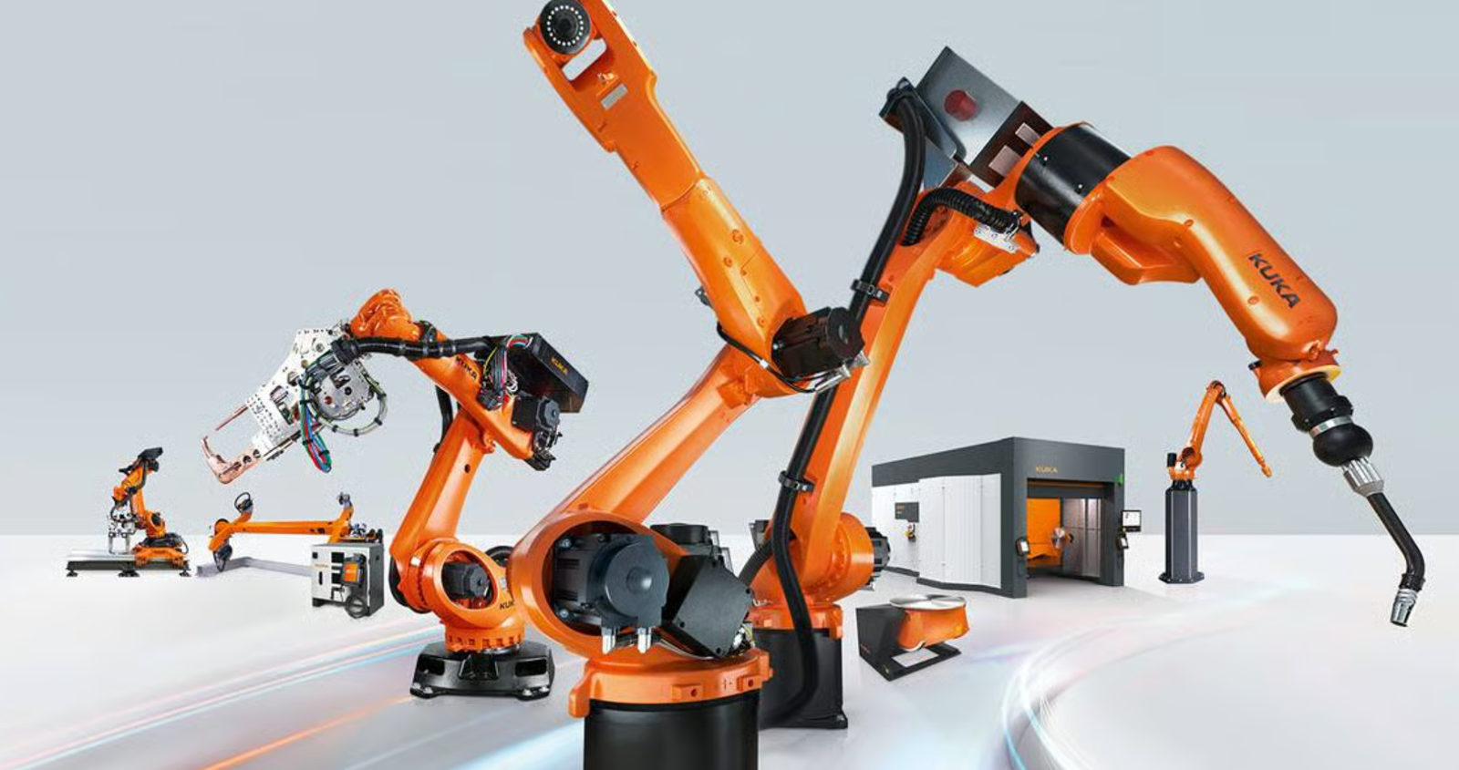
Scope: this page selects robot-cell architecture—6-axis industrial arm, collaborative arm, positioner, turntable and linear track—plus fixtures, sensing and ISO 10218 safety. The existing laser welding machine guide compares handheld, automatic and robotic laser processes; the robot welding product page presents the machine configuration.
A robot welding machine purchase is rarely a robot purchase — it is a welding cell purchase. The robot arm is one of seven components that decide quality, cycle time, payback and safety: arm, welding power source (MIG / MAG / TIG / laser), torch, fixture, positioner, seam-tracking sensor and safety cell. Pick the right combination and a stable assembly pays back in 6–14 months. Pick the wrong combination — wrong arm reach, wrong process for the material, no positioner where one was needed — and the cell underperforms manual welding for the first 6 months.
This guide walks through the three robot routes (6-axis industrial robot, collaborative robot / cobot, multi-axis cell with positioner or external track), the four welding processes (laser / MIG / TIG / hybrid), and the HORISTAR RW-10 reference configuration — a 6-axis robot welding cell with international-brand arm (ABB / FANUC / KUKA / YASKAWA), integrated ±180° positioner, ±0.05 mm robot repeatability and laser seam tracking. By the end of this guide you should be able to write a robot welding RFQ that returns quotations close to the final price.
HORISTAR buyers start with the Robot Welding Machine product page and the broader laser welding machine category. Send drawings, 3D files, material, joint type, weld length, monthly output and current welding method before requesting a quote — the cell decision depends on all of these together.
By: Doris Li, HORISTAR CNC Application Team. Doris is a CNC Application Engineer with 8+ years guiding overseas buyers across 30+ countries on machine selection, sample testing, RFQ writing and pre-shipment inspection. See author profile →
Updated: 2026-08-27 · Estimated read time: 14 minutes · Reviewed by: HORISTAR Robot & Welding Application Team
Key Takeaways
- Robot welding is a cell decision, not an arm decision. Arm + welding process + fixture + positioner + sensor + safety cell — change any one and the result changes.
- 6-axis industrial robot is the default for repeated assemblies above ~160 welding hours/month. Best balance of speed, reach and payback.
- Collaborative robot (cobot) is for lighter, lower-speed work with frequent part changes — only after a task-based ISO/TS 15066 risk assessment because welding hazards (arc light, fumes, hot parts, laser energy) don't disappear because the robot is collaborative.
- Multi-axis cell with positioner is the right answer when one clamp can't present all seams — typically when the part has welds on 3+ sides or exceeds 1000 mm.
- Welding process choice is as important as robot choice. Laser welding (deep narrow weld, low distortion), MIG/MAG (high deposition, structural), TIG (highest quality, slower), hybrid (laser + MIG). Match process to material and joint, not to robot brand.
- HORISTAR RW-10 reference cell: ABB / FANUC / KUKA / YASKAWA 6-axis arm + ±180° positioner + laser seam tracking, 10 kg wrist payload, 2018 mm reach, ±0.05 mm robot repeatability, ±0.1 mm positioner repeatability. Supports MIG, TIG, laser welding processes.
- Real payback for repeated assemblies typically lands at 6–14 months when monthly welding hours exceed 160. Below 80 hours/month, a manual or semi-automatic route is usually the right answer.
- Safety planning references ISO 10218-1 (robots), ISO 10218-2 (cell integration), ISO/TS 15066 (collaborative), plus ISO 12100, ISO 13849-1, ISO 14120, OSHA robot guidance and EN 60204-1 / IEC 60204-1.12345678
Three Robot Routes: Which Cell Fits Your Production
The first decision is the cell route. Robot brand comes later.
| Robot route | Best fit | Monthly weld hours | Capex band | Decision rule |
|---|---|---|---|---|
| 6-axis industrial robot | Repeated brackets, frames, housings, structural assemblies | 160+ hours/month | USD 35k–95k for a basic cell | Strongest payback on stable repeated parts |
| Cobot welding cell | Lighter parts, slower process, mixed batches, shared workspace | 40–160 hours/month | USD 28k–65k | Only after ISO/TS 15066 task risk assessment |
| 6-axis + 1-axis positioner | One heavy part needs rotation during welding | 160+ hours/month | USD 50k–120k | Rotation removes 1+ manual flip |
| 6-axis + 2-axis positioner (HORISTAR RW-10) | Multi-side seams on a fixture | 200+ hours/month | USD 65k–140k | Torch angle fails on 2+ sides without rotation |
| 6-axis + dual-station table | Same part runs in batches; loading time is a bottleneck | 240+ hours/month | USD 80k–180k | Loading time > 20% of cycle |
| Robot on linear track | Large parts > 2000 mm; multiple workstations | 240+ hours/month | USD 100k–250k | One arm covers multiple cells |
Source: HORISTAR robot welding cell-sizing practice, 2026.
The honest rule: if monthly welding hours sit below 80, a robot cell does not pay back. The right answer at that volume is a semi-automatic fixture + skilled welder, or a smaller cobot trial — not a full industrial robot cell.
Welding Process: Choose Before the Robot
The welding process drives torch weight, power supply size, fume control, distortion control and fixture design. Pick the process by material and joint, then size the robot.
| Process | Strength | Weakness | Best fit |
|---|---|---|---|
| MIG / MAG | High deposition rate, structural welds, forgiving of joint fit | Spatter, more heat input, more distortion | Carbon steel structural fab, automotive chassis, agricultural equipment, heavy fab |
| TIG (GTAW) | Highest quality, narrow HAZ, no spatter | Slower (~25–40% of MIG speed), more skill needed | Stainless food/medical, aluminium, thin material, cosmetic welds |
| Laser welding (fiber, 1–6 kW) | Deep narrow weld, very low distortion, ~3–10× faster than MIG on thin material, no filler on autogenous joints | Tight fit-up tolerance, higher capex, requires laser safety | Stainless thin sheet, white-goods bodies, EV battery enclosures, automotive trim, exhaust components |
| Laser-MIG hybrid | Combines laser speed with MIG gap-bridging | High complexity, highest capex | Shipbuilding, pipeline, structural fab where laser-only fit-up is impractical |
| Pulse MIG / RMD | Lower heat input than standard MIG, better thin material | More expensive power supply | Thin sheet structural, aluminium |
The HORISTAR RW-10 supports MIG, TIG and laser welding processes with German-brand power supplies. The base configuration ships with the buyer's choice — confirm during quotation.
Process selection by material
| Material | First-choice process | Second-choice | Avoid |
|---|---|---|---|
| Carbon steel structural (3–20 mm) | MIG / MAG | Laser-MIG hybrid | TIG (too slow) |
| Stainless 304/316 thin (0.8–3 mm) | Laser welding | Pulse TIG | Standard MIG (too much distortion) |
| Stainless thick (3–10 mm) | Pulse MIG | Laser-MIG hybrid | — |
| Aluminium 5052/6061 thin | TIG / Pulse MIG | Laser welding | Standard MIG (porosity) |
| Aluminium thick (5+ mm) | Pulse MIG | Laser-MIG hybrid | — |
| Galvanised steel | Pulse MIG (CMT-style) | Laser welding | Standard MIG (zinc fume + porosity) |
| White goods panels (0.6–1.2 mm) | Laser welding | TIG | Standard MIG |
| Battery enclosures / busbars | Laser welding | Pulse TIG | — |
Source: HORISTAR welding process review across 2024–2026 RFQ database.
The single most common buyer mistake: ordering a MIG robot cell for stainless thin sheet work, then complaining about distortion. The robot did not cause the distortion — MIG is the wrong process for that material at that thickness. Laser welding would have given a flat panel in half the cycle time.
6-Axis Robot Welding: The Default Workhorse
A 6-axis industrial robot welding cell is the default automation route for repeated assemblies above ~160 welding hours per month. The six axes (shoulder pitch + yaw, elbow pitch, wrist pitch + yaw + roll) let the torch reach around brackets, frames and complex assemblies without re-clamping.
The mechanism is path repeatability. Once the part is clamped in the same location, the robot repeats the programmed weld path. This eliminates operator travel-speed variation — the #1 cause of weld quality variation in manual production. But it also repeats fixture errors. A poor fixture creates the same bad weld on every part faster than a manual process. Fixture quality matters more than robot brand.
| Buyer input | 6-axis robot planning value | Why it matters |
|---|---|---|
| Payload (wrist) | 6–20 kg (torch + cable + collision margin) | Must include torch weight + cable weight + 20% margin for collision tolerance |
| Reach | 1400–2500 mm common band | Must cover all seams without entering singularity |
| Repeatability | ±0.05 to ±0.1 mm | Limits how tight a joint fit-up the cell can hold |
| Joint speeds | J1–J6 typically 100–250°/s | Drives cycle time on multi-pass welds |
| Joint range | J1 ±165°, J6 ±360° typical | Determines how the arm wraps around the part |
| Wrist torque | J4 30–50 Nm, J5 20–30 Nm, J6 7–10 Nm | Required for laser welding head + cable assembly |
| Brand ecosystem | ABB / FANUC / KUKA / YASKAWA | Service support and operator availability in destination country |
Source: HORISTAR 6-axis robot welding cell-sizing practice, 2026.
Collaborative Robot (Cobot) Welding: When and Only When
A collaborative robot welding system fits only when the full application is collaborative — not just because the robot brand is sold as a cobot. ISO/TS 15066 supplements ISO 10218-1 and ISO 10218-2 specifically for collaborative robot systems and their work environment.
For welding, the collaborative risk assessment must cover: arc light or laser energy exposure, hot parts and torch tip, weld fume (zinc, stainless chromium VI, mild steel manganese), pinch points, sharp workpiece edges, torch cable drag, shared-space pedestrian access, emergency stop accessibility. A collaborative arm does not remove the need for guarding, extraction, PPE or interlocks when the welding process creates these hazards.
| Condition | Cobot direction | Decision rule |
|---|---|---|
| Part weight | Below 10 kg | Better when parts move by hand without hoist |
| Monthly weld time | 40–160 hours/month | Stronger when flexibility matters more than peak speed |
| Path speed | Lower (typically < 1 m/min weld speed in collaborative mode) | Use after task risk assessment, not catalogue speed |
| Part changeover | 2+ part families/week | Cobot-style teaching helps flexible batches |
| Process | TIG or low-power laser | Lower fume + lower heat = easier collaborative case |
| Floor space | Limited, shared with operators | Cobot's small footprint helps |
| Safety scope | Task-based assessment documented | ISO/TS 15066 + ISO 10218 + site controls required |
The honest answer most cobot welding pitches don't include: even with a collaborative arm, the welding process is rarely collaborative. Arc light requires curtains; fume requires extraction; hot parts require keep-out zones. So most cobot welding cells end up with the same guarding cost as a small 6-axis cell, but with lower welding speed. The case for cobot welding is flexibility and small footprint, not "skip the guarding".
Source: ISO/TS 15066, OSHA robot guidance and HORISTAR collaborative welding planning practice, 2026.
Multi-Axis Cell: Positioner, Turntable, Track
A multi-axis robot welding cell is better when moving the part improves access more than stretching the robot path. A positioner, turntable or external track changes the weld posture so the torch keeps a stable angle, shielding gas coverage stays consistent, and fixtures need fewer manual flips.
The mechanism is weld presentation. If the seam points away from the torch or forces long wrist rotation, the robot path becomes awkward and weld quality degrades. A positioner rotates the part so each seam meets the torch at the optimal angle (usually within 15° of horizontal flat for MIG, or within 5° for high-speed laser).
| Cell type | External motion | Best-fit part | Decision rule |
|---|---|---|---|
| 6-axis only | 0 external axes | Simple frames, brackets, panels | Every seam reachable in 1 clamp |
| Robot + turntable (1-axis) | 1 rotation axis (≤ ±180°) | Circular weld, 2-side seams | Rotation removes 1+ manual flip |
| Robot + head-tailstock positioner (1–2 axis) | Tilt + rotation | Long frames, tubular assemblies > 1000 mm | Part length > 1000 mm |
| Robot + 2-station table (HORISTAR RW-10) | Index between 2 work zones | Repeated part families, batch production | Loading time > 20% of cycle |
| Robot on track + positioner | Travel + tilt + rotation | Large frames > 2500 mm, multi-station | One arm covers 2+ workstations |
| Coordinated motion (synchronised) | Multiple axes moving together during weld | Complex curved seams (impeller, pipe-flange) | Required when seam follows compound curve |
Source: HORISTAR multi-axis robot welding cell planning practice, 2026.
The HORISTAR RW-10 layout
The RW-10 is HORISTAR's reference 6-axis + 2-axis-positioner cell. While the robot welds on one side of the positioner, the operator loads the next part on the other side — the positioner indexes ±180° at 20°/s. Load and weld run in parallel, which is the structural reason this configuration outperforms a single-station cell on repeated parts.
HORISTAR RW-10 Reference Specifications
This is HORISTAR's published reference configuration. Final specification depends on the buyer's process choice (MIG / TIG / laser), payload required, fixture design and floor space.
| Specification | HORISTAR RW-10 |
|---|---|
| Robot brand options | ABB / FANUC / KUKA / YASKAWA (buyer choice) |
| Robot degrees of freedom | 6-axis |
| Wrist payload | 10 kg |
| Maximum working radius | 2018 mm |
| Robot repeatability | ±0.05 mm |
| Robot weight | 180 kg |
| Positioner rotation diameter | 1000 mm |
| Positioner rotation angle | ±180° |
| Positioner rotation speed | 20°/s |
| Positioner rated load capacity | 1000 kg |
| Positioner repeatability | ±0.1 mm |
| Positioner axis centre height | 750 mm |
| Safe rotation height | 150 mm |
| Robot joint speeds (J1–J6) | 150°/s each |
| Robot joint range | J1 ±165°, J2 +155°/−90°, J3 +85°/−185°, J4 ±185°, J5 ±120°, J6 ±360° |
| Robot wrist torque | J4 33 Nm, J5 23.2 Nm, J6 7.5 Nm |
| Robot wrist inertia | J4 0.9 kg·m², J5 0.5 kg·m², J6 0.15 kg·m² |
| Power supply | Three-phase 200V ±10%, 50Hz |
| Insulation class | Class H |
| Welding power source | MIG / TIG / laser — German-brand power source standard |
| Seam tracking | Laser sensor seam tracking (optional but recommended) |
| Control system | Intelligent CNC interface, multi-agent coordination |
| Operating temperature | 0–40 °C |
| Compliance | ISO 10218-1/-2, CE, FDA |
Source: HORISTAR Robot Welding Machine product page, 2026.
Why these specifications matter to the buyer:
- ±0.05 mm robot + ±0.1 mm positioner repeatability — combined cell repeatability is what limits the joint fit-up tolerance the buyer can run on the cell.
- 10 kg wrist payload — covers most MIG/TIG torches and most fiber laser heads up to ~3 kW. Heavier laser heads (6 kW+) may need a larger arm — discuss during RFQ.
- 2018 mm reach + 1000 mm positioner diameter — handles parts up to ~1.8 m diagonal comfortably; larger parts need a track or robot upgrade.
- ±180° positioner at 20°/s — load-and-weld parallel workflow is standard, not optional.
- Brand choice (ABB / FANUC / KUKA / YASKAWA) — buyer chooses based on service availability in their country (ABB strong in Europe, FANUC strong in Japan/USA/Korea, KUKA strong in Germany/EU/Asia, YASKAWA strong globally). HORISTAR is brand-agnostic; the recommendation is to pick the brand with the strongest local service presence.
Seam Tracking: Why Laser Sensors Pay Back Within Months
This is one of the under-discussed features that decides robot welding reliability in production.
The problem: even with a good fixture, real production parts have small variations — laser-cut blanks have ±0.1 mm cut tolerance, formed parts have springback variation, structural fab has weld distortion from earlier joints. The robot path is rigid; the real part isn't. Without seam tracking, the cell needs perfect fixtures + perfect blanks + zero accumulated distortion. With seam tracking, the robot finds the actual seam location and adjusts the path in real time.
| Seam tracking technology | How it works | Best for |
|---|---|---|
| Laser line sensor (HORISTAR standard option) | Laser line projected ahead of torch; CCD camera measures seam offset; controller adjusts path | All robotic welding — most universal |
| Through-arc seam tracking (TAST) | Robot weaves slightly during weld; current variation indicates seam centre | MIG/MAG only, no extra hardware |
| Vision (camera + AI) | Camera identifies seam features pre-weld | Complex / multi-pass / unknown fit-up |
| Touch sensing | Robot touches part edges to locate before welding | First pass on large parts, lower production speed |
The ROI logic: laser seam tracking adds USD 8–18k to a cell. On a cell making 8,000 parts/year with a 1.5% rework rate from seam-tracking issues, eliminated rework saves typically USD 12–30k/year — payback in 6–12 months. HORISTAR strongly recommends laser seam tracking for any production cell running > 100 parts/month.
Source: HORISTAR seam-tracking review and RFQ practice, 2026.
ROI Calculation: When Robot Welding Pays Back
This is the calculation HORISTAR runs with overseas buyers during quotation review. Replace each input with your own numbers.
Scenario: a metal fabricator considering robot welding for a repeated steel frame assembly. Current production: manual MIG welding by 2 welders, 220 welding hours/month.
Inputs
- Manual welding time: 220 hours/month
- Robot welding cycle time (same parts, after fixture optimisation): 115 hours/month
- Robot programming + fixture adjustment (after initial setup amortised): 8 hours/month
- Net welding time saved: 220 − 115 − 8 = 97 hours/month
- Loaded labour rate: USD 18/hour (welder + overhead in developed market) or USD 8/hour (emerging market)
- Quality cost reduction (less rework + less scrap): ~30% reduction typical
- Current rework cost: USD 280/month → saved USD 84/month
- Cell capex (RW-10 mid-spec with laser seam tracking + MIG package + fixture): USD 65,000
- Fixture engineering + commissioning: USD 4,800 (included in cell capex if quoted complete)
- Planning horizon: 12 months
Formula
Monthly value = labour saved + rework saved − robot operating cost (~USD 50/month consumables + electricity)

Payback months = total cell capex ÷ monthly value
Substitution (developed market, USD 18/hour labour)
- Labour saved: 97 × USD 18 = USD 1,746/month
- Rework saved: USD 84/month
- Operating cost: −USD 50/month
- Monthly value: USD 1,780/month
- Payback on USD 65k cell: 65,000 ÷ 1,780 ≈ 36 months
Substitution (emerging market, USD 8/hour labour)
- Labour saved: 97 × USD 8 = USD 776/month
- Rework saved: USD 84/month
- Operating cost: −USD 50/month
- Monthly value: USD 810/month
- Payback on USD 65k cell: 65,000 ÷ 810 ≈ 80 months
Reading this honestly: robot welding pays back fastest in high-labour-cost markets. In USD 18/hour markets, payback under 36 months is realistic; in USD 25–40/hour markets (Western Europe, North America, Australia) payback can drop to 18–24 months. In USD 5–10/hour markets, payback typically lands at 5–8 years — and the case for automation has to be made on quality consistency, throughput ceiling, and welder availability rather than direct labour savings.
Recommendation: if your monthly labour saved × labour rate exceeds USD 1,500/month, robot welding deserves a sample test. If it lands below USD 600/month, manual or semi-automatic remains the right answer at current labour cost.
Source: HORISTAR robot welding automation planning example, 2026. Anonymised from RFQ data 2024–2026; capex ranges are indicative, not binding quotations.
Anonymised Case Snapshots from the HORISTAR RFQ Desk
Case A — Automotive bracket maker, Eastern Europe, 2025. 380 brackets/day on 3 SKUs, MIG welding on carbon steel 3–5 mm. Welding hours: 240/month with 3 welders. HORISTAR RW-10 with MIG + laser seam tracking + 2-axis positioner. Programming + fixturing took 3 weeks. Result: 380 brackets/day on 1 operator at the loading station; payback in 14 months on labour + 22% rework reduction. Welder availability had been the bottleneck — that disappeared in week 2.
Case B — Stainless food equipment maker, Western Europe, 2024. Asked for "robot MIG welding cell" for thin (1.5 mm) stainless food-grade enclosures. HORISTAR's honest answer: MIG is the wrong process for this material at this thickness. Standard MIG would cause distortion, weld spatter contamination (food contact surfaces) and finish-grinding cost that erases the labour saving. Recommendation: 6-axis robot + fiber laser welding head (2 kW) + positioner. Cycle time per enclosure: 4 minutes (vs 11 minutes manual TIG); no spatter; no finish grinding required. Decision: laser-based cell. Payback in 9 months — driven by finishing labour elimination, not just welding labour.
Case C — Agricultural implement OEM, South America, 2025. Wanted "cheapest robot welding cell for small-batch production". Monthly volume: 65 hours. HORISTAR's honest answer: at 65 hours/month, no robot cell pays back at your labour cost. Recommendation: a semi-automatic fixture + skilled welder, and revisit robot welding when volume passes 150 hours/month. The buyer initially pushed back, then ran the math themselves. Two years later they came back at 220 hours/month and ordered the RW-10. The right "no" earned the right "yes" later.
Case D — Battery enclosure manufacturer, East Asia, 2026. Aluminium 5052 battery box welding, 6,000 units/month. Tight HAZ requirement (< 1.0 mm wide); no porosity tolerance. Process: pulse fiber laser welding only — MIG creates porosity in aluminium, TIG is too slow at this volume. Cell: 6-axis robot + laser welding head + 2-axis positioner + laser seam tracking. Payback: 7 months on yield improvement alone (porosity rejection dropped from 4.2% manual TIG to 0.6% robot laser).
These are not testimonials. They describe how HORISTAR runs robot welding RFQs — including the cases where the right answer is laser instead of MIG, or "wait a year" instead of "buy now".
ISO 10218 Safety Framework for Robot Welding Cells
Robot welding safety must cover the robot, welding process hazards, fixture, electrical cabinet, fume extraction and human access points. OSHA's industrial robot guidance emphasises robot system hazards, safeguarding and risk assessment; ISO 10218-2 focuses on cell-level integration.
| Safety element | Standard reference | HORISTAR RW-10 evidence |
|---|---|---|
| Robot arm safety | ISO 10218-1 | Robot from ABB/FANUC/KUKA/YASKAWA — all comply with ISO 10218-1 |
| Robot cell integration | ISO 10218-2 | Cell layout, safeguarding, access zones documented |
| Collaborative operation (if applicable) | ISO/TS 15066 | Task risk assessment required for any collaborative configuration |
| Machinery risk assessment | ISO 12100 | Documented risk-reduction logic with hazard list |
| Safety control category | ISO 13849-1 PL d / Category 3 or 4 | Light curtain + interlock fence + e-stop on dual channel |
| Guarding | ISO 14120 | Fixed fence around cell + light curtain at operator interface |
| Welding light (UV/IR) | Welding curtain + extraction at source | Standard cell includes curtain panels |
| Welding fume | OSHA PEL + ACGIH TLV + LEV with HEPA | Extraction with HEPA H13/H14 standard for stainless / galvanised |
| Laser welding safety | IEC 60825-1 Class 4 | OD-rated viewing windows + interlocks (if laser process selected) |
| Electrical equipment | EN 60204-1 / IEC 60204-1 | Cabinet, grounding, wiring documentation |
| US workplace compliance | OSHA 29 CFR 1910 Subpart Q (welding) + OSHA robot guidance | Documented for US destinations |
| Compliance documents | CE, ISO, FDA | HORISTAR company-level certifications |
Source: HORISTAR robot welding safety practice, 2026, referencing ISO, IEC and OSHA sources listed below.
A critical note for laser welding cells: when the welding process is fiber laser (not MIG/TIG), the cell becomes an IEC 60825-1 Class 4 laser system with all the goggles, interlock and access-zone requirements that come with Class 4 lasers. HORISTAR builds laser welding cells with the appropriate OD-rated viewing windows and interlocks — this must be specified at RFQ stage, not added later.
Lifecycle and Maintenance Matrix (5-Year Window)
| Maintenance interval | 6-axis robot cell | Cobot cell | Multi-axis (RW-10) cell |
|---|---|---|---|
| Torch + nozzle inspection | Every shift | Every shift | Every shift |
| Torch cable wear check | Weekly | Weekly | Weekly |
| Fixture locating point check | Every 40 hours | Every 40 hours | Every 40 hours |
| Seam tracking sensor cleaning | Every 40 hours | Every 40 hours | Every 40 hours |
| Positioner reducer + bearing check | N/A | N/A | Every 3 months |
| Safety interlock test | Monthly | Monthly | Monthly |
| Program backup | Monthly | Monthly | Monthly |
| Path + quality audit | Every 6 months | Every 3 months | Every 6 months |
| Robot encoder zero-point verification | Yearly | Yearly | Yearly |
| Robot reducer service | Per OEM (typically 20,000 hours) | Per OEM | Per OEM |
| Fume extraction filter replacement | Per manufacturer | Per manufacturer | Per manufacturer |
| Annual safety audit | Yearly | Yearly | Yearly |
| Lifecycle planning horizon | 5–7 years | 5–7 years | 5–7 years |
Source: HORISTAR robot welding ownership planning practice, 2026.
Sample Welding Test Before Purchase
A robot welding sample test must prove the cell, not just the robot. Testing a freehand sample with the robot proves nothing.
| Test item | Minimum evidence | Acceptance direction |
|---|---|---|
| Materials | 3 materials in scope | Carbon steel + stainless + aluminium / galvanised |
| Thicknesses | 3 thicknesses | Thinnest, routine, thickest |
| Joint types | 3 joints | Butt + lap + corner / T-joint |
| Process confirmation | Same process as production | MIG / TIG / laser — not "MIG demo for a laser order" |
| Fixture repeatability | 5 clamp/unclamp cycles | Part returns to the same seam position ± fit-up tolerance |
| Robot path | 5 repeated weld cycles | Torch path and seam location stay stable |
| Seam tracking (if specified) | Test with intentional ± 0.5 mm offset blanks | Sensor adjusts path; weld lands in seam |
| Cycle time | Measured on production part | Real number, not catalogue |
| Cross-section / NDT (if required) | 1 cross-section per joint type | Penetration + porosity + HAZ width |
| Runtime | 2-hour trial | Surfaces cable, fume, cycle and operator-flow issues |
| Pre-shipment evidence | Video + cross-section + cycle time report | Standard HORISTAR evidence pack |
Source: HORISTAR robot welding sample-test practice, 2026.
RFQ Input List
To request a quote, send HORISTAR:
- Part drawings + 3D files (STEP / IGES preferred)
- Material grade and thickness for each joint
- Joint types and weld length per joint
- Required weld quality standard (AWS D1.1 / AWS D1.6 / ISO 5817 / customer spec)
- Monthly production volume per SKU
- Target cycle time per assembly
- Current welding method (manual MIG / TIG / laser / SMAW) + current cycle time
- Welder labour cost in destination country
- Fixture preference (HORISTAR design / buyer-supplied / hybrid)
- Process preference if known (MIG / TIG / laser / hybrid)
- Robot brand preference if any (ABB / FANUC / KUKA / YASKAWA / no preference)
- Floor space available (length × width × ceiling height)
- Voltage and frequency
- Destination country (for compliance + service network selection)
- Safety document requirements (CE / OSHA / customer-specific)
Related guides: Handheld Laser Welding vs TIG / MIG, How to Choose a Laser Welding Machine, Laser Cleaning Machine for Rust, Paint and Surface Preparation, and Automatic Laser Welding Machine for projects not ready for a full robot cell.
Specification Checklist
| Specification | What to request | Why it protects the buyer |
|---|---|---|
| Robot brand + model | ABB / FANUC / KUKA / YASKAWA — match to destination service network | Confirms parts + support availability |
| Wrist payload | kg incl. torch + cable + 20% margin | Prevents arm undersizing |
| Reach | mm matched to part size + fixture | Avoids singularity |
| Repeatability | ±0.05 to ±0.1 mm | Limits joint fit-up requirement |
| Positioner | Rated load + rotation angle + repeatability | Multi-side seam access |
| Welding process | MIG / TIG / laser / hybrid | Defines power supply + safety package |
| Welding power supply | German-brand standard on RW-10 | Reliability + spare parts |
| Seam tracking | Laser sensor (recommended) | Real-world fit-up tolerance |
| Fixture | HORISTAR-designed with locating + clamping | Controls seam location |
| Safety cell | Fence + light curtain + e-stop + ISO 10218-2 layout | Compliance |
| Fume extraction | LEV with HEPA H13/H14 | Stainless / galvanised mandatory |
| Laser safety (if laser) | OD windows + interlocks + IEC 60825-1 Class 4 documentation | Required for laser welding cells |
| Sample weld | Cross-section + cycle time + 5 repeated parts | Proves the cell, not the catalogue |
| Training | Operator + programming + safety | Reduces week-1 risk |
| Warranty | 2-year warranty, lifetime tech support, 18-hour response | HORISTAR standard service commitment |
| Compliance | CE, ISO 10218-1/-2, FDA + customer-specific welding code | Required for EU / North America |
Frequently Asked Questions
Source: HORISTAR robot welding selection and sample-testing practice, 2026.
What is a robot welding machine?
A robot welding machine is an automated welding cell built around a 6-axis (or cobot, or multi-axis) robot arm that carries a welding torch — MIG, TIG, laser or hybrid. The cell also includes a welding power source, fixture, positioner (often), seam-tracking sensor (recommended), safety cell with guarding and fume extraction. Weld quality depends on every component, not just the arm — robot welding is a cell purchase, not just a robot purchase.
When should I choose a 6-axis robot welding machine?
Choose a 6-axis robot welding machine when a repeated part needs programmed torch access from several angles and monthly welding time is above ~160 hours. The cell is strongest when the same assembly runs 6–24 months and the fixture locates every part consistently. Below 80 welding hours/month, manual or semi-automatic welding is usually the right answer.
Where does a collaborative robot welding system fit?
A cobot welding system fits lighter (< 10 kg), lower-speed and higher-changeover welding tasks only after a task-based risk assessment per ISO/TS 15066 and ISO 10218. A cobot does not automatically eliminate guarding — arc light, fume, hot parts and torch movement still require curtains, extraction, PPE and access controls. The case for cobot welding is flexibility and small footprint, not "skip the safeguarding".
When is a multi-axis robot welding cell worth the extra capex?
A multi-axis cell with positioner is worth it when moving the part improves access more than stretching the robot path. Add a 1-axis or 2-axis positioner when one clamp cannot present all seams, when part length exceeds ~1000 mm, or when loading time exceeds 20% of cycle time. The HORISTAR RW-10 includes a ±180° positioner standard — load and weld run in parallel, doubling effective throughput vs single-station cells.
Laser welding vs MIG vs TIG on a welding robot — which is right?
MIG/MAG is the right process for carbon steel structural fabrication, thicker material (3+ mm), and parts where deposition rate matters. TIG is the right process for highest-quality welds on stainless, aluminium and cosmetic seams — but is ~25–40% slower than MIG. Laser welding is the right process for thin material (0.6–3 mm), stainless/aluminium where distortion matters, white-goods bodies and battery enclosures — typically 3–10× faster than MIG on the right material. Pick the process by material and joint, not by robot brand.
What's the typical payback for robot welding?
Payback depends on labour cost in your market. At USD 18/hour loaded labour: 18–36 months. At USD 25–40/hour (Western Europe, North America, Australia): 12–24 months. At USD 5–10/hour (most emerging markets): 5–8 years — at this labour cost, the case for robot welding has to be quality consistency, throughput ceiling and welder availability rather than direct labour savings. As a screening rule, if monthly labour saved × labour rate exceeds USD 1,500/month, robot welding deserves a sample test.
Why does HORISTAR recommend laser seam tracking on production cells?
Because real production parts have small variations (cut tolerance, springback, weld distortion) that rigid robot paths cannot accommodate. Without seam tracking, the cell requires perfect fixtures + perfect blanks + zero accumulated distortion — which is unrealistic. Laser seam tracking adds USD 8–18k to a cell capex but typically saves USD 12–30k/year in rework on cells running 100+ parts/month. Payback is 6–12 months on production cells.
What information should I send HORISTAR for a robot welding quotation?
Send part drawings + 3D files, material grade and thickness per joint, joint types, weld length per joint, required weld quality standard (AWS D1.1 / D1.6 / ISO 5817), monthly production volume per SKU, target cycle time, current welding method and cost, fixture preference, process preference, robot brand preference, floor space, voltage, destination country, and safety document requirements. HORISTAR returns a recommended cell configuration, fixture concept, sample-test plan and pre-shipment evidence list.
Does HORISTAR provide ISO 10218 and CE compliance documentation?
Yes. HORISTAR robot welding cells are documented against ISO 10218-1 (robot arm) and ISO 10218-2 (cell integration), with ISO/TS 15066 (collaborative) for cobot configurations. Additional documentation covers ISO 12100 (risk assessment), ISO 13849-1 (safety control category), ISO 14120 (guards), EN 60204-1 / IEC 60204-1 (electrical). For US destinations, OSHA 29 CFR 1910 Subpart Q welding compliance and OSHA robot guidance are included. For laser welding cells, IEC 60825-1 Class 4 documentation. HORISTAR holds ISO, CE and FDA approvals at the company level.
Review Record
Technical review by the HORISTAR Robot & Welding Application Team, 2026-08-27. Scope included three-route cell selection (6-axis vs cobot vs multi-axis), welding process selection across MIG / TIG / laser / hybrid with material match matrix, HORISTAR RW-10 specification verification against the HORISTAR product page (ABB/FANUC/KUKA/YASKAWA arm, 10 kg payload, 2018 mm reach, ±0.05 mm robot repeatability, ±0.1 mm positioner repeatability, ±180° positioner with 1000 kg load), laser seam-tracking ROI, ISO 10218-1/-2 + ISO/TS 15066 safety mapping, ROI calculation across developed and emerging labour markets, four anonymised case snapshots (automotive bracket, stainless food, ag implement "wait a year", aluminium battery), sample-test protocol and RFQ input list. This guide is re-reviewed at least once per year.
Sources
-
International Organization for Standardization, ISO 10218-1:2025 Robotics — Safety requirements — Part 1: Industrial robots. ↩
-
International Organization for Standardization, ISO 10218-2:2025 Robotics — Safety requirements — Part 2: Industrial robot applications and robot cells. ↩
-
International Organization for Standardization, ISO/TS 15066:2016 Robots and robotic devices — Collaborative robots. ↩
-
International Organization for Standardization, ISO 12100:2010 Safety of machinery — Risk assessment and risk reduction. ↩
-
International Organization for Standardization, ISO 13849-1:2023 Safety-related parts of control systems. ↩
-
International Organization for Standardization, ISO 14120:2015 Safety of machinery — General requirements for guards. ↩
-
Occupational Safety and Health Administration, Industrial robot systems and industrial robot system safety. ↩
-
International Electrotechnical Commission, IEC 60204-1:2016 Electrical equipment of machines. ↩
-
HORISTAR, Robot Welding Machine. ↩