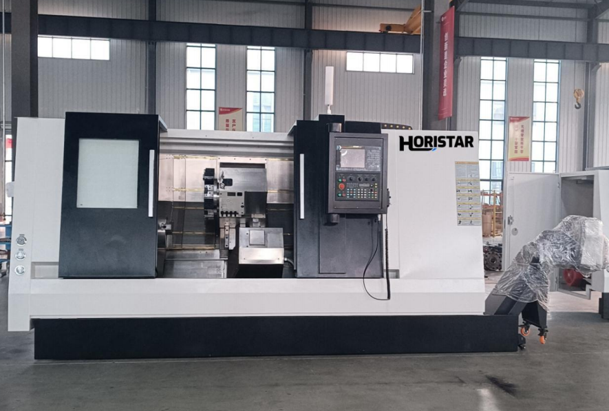
- Choose a servo turret CNC lathe when the part needs 4 or more tools, repeated batches or tight process control. Simple one-off turning can still be handled on a lower-automation lathe.
- Do not judge accuracy from the turret alone. Use ISO-style positioning, geometric and finished-piece checks when comparing CNC turning machines.
- For HORISTAR TCK-series selection, start with part diameter, length and bar size. Published TCK-series figures include 560–800 mm swing over bed, 300–600 mm maximum cutting diameter, 65–80 mm spindle bore and a 12-station servo power turret.
- A 12-station turret is useful when one cycle includes turning, boring, drilling, grooving, threading, chamfering and parting. The value is lower if a part uses only 1 or 2 tools.
- Request a sample cut or pre-shipment trial cut for precision parts. Agree on material, tolerance, measuring tools, surface roughness method and cycle count before the test.
What Is a Servo Turret CNC Lathe?
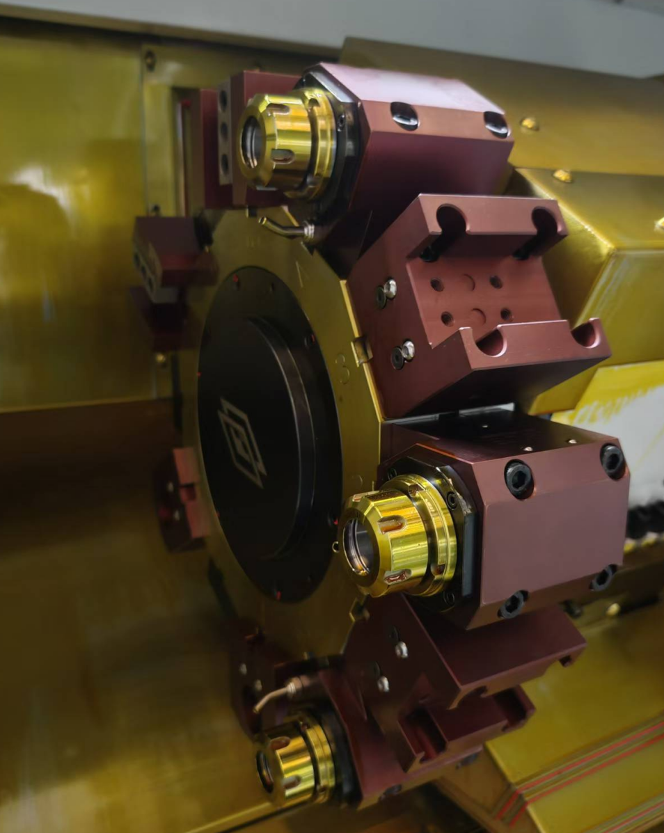
A servo turret CNC lathe is a CNC turning machine that uses a servo-controlled turret to index multiple cutting tools into position automatically. The turret holds tools for facing, OD turning, ID boring, drilling, grooving, threading, chamfering and parting, so a part can move through several operations in one programmed cycle. HORISTAR’s current turning-machine range is introduced on the HORISTAR CNC Lathe Machine page; final model choice should be based on the drawing, material and target output.
The servo motor controls turret movement, but the mechanical lock is what resists cutting load after indexing. Servo control helps the turret reach the station quickly and consistently; the clamping and coupling mechanism keep the tool from moving while the insert is under radial or axial force.
For buyers, the practical question is not “does it have a servo turret?” The practical question is whether the turret, chuck, spindle and bed can hold the required tolerance on your material for your batch size.
When a Servo Turret Is Worth Paying For
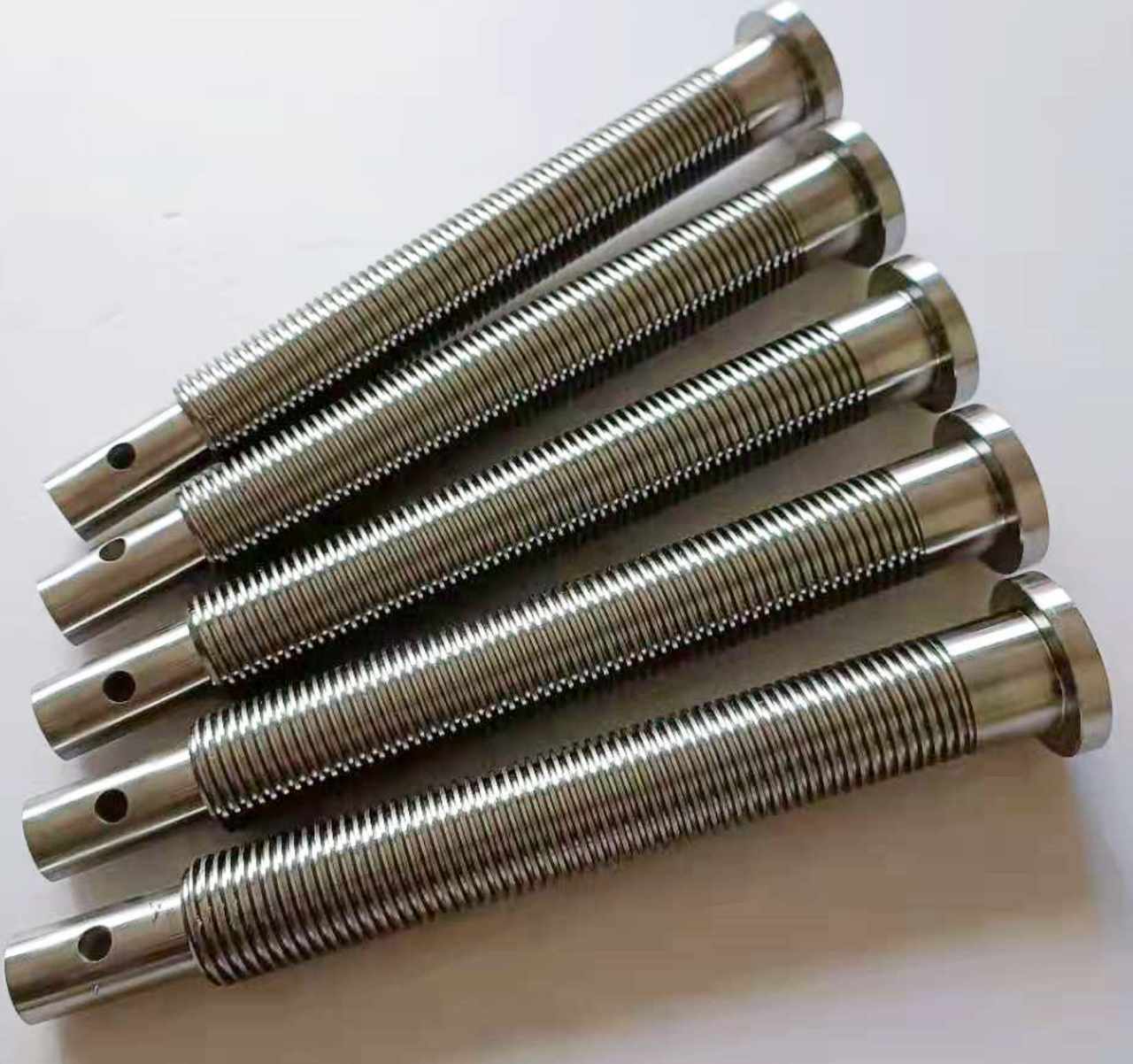
A servo turret is worth paying for when automatic tool indexing removes enough manual work, setup risk or cycle delay to improve the real production flow. Use this quick rule for first screening before a trial cut:
| Production Condition | Servo Turret Value | Buying Decision |
|---|---|---|
| 1–2 tools, prototype or repair work | Low | A simpler lathe may be enough when monthly volume is below 100 pieces. |
| 3–5 tools, repeated small batches | Medium | Compare setup time and labor cost when each batch is 100–500 pieces. |
| 6–10 tools, daily batch production | High | Servo turret is usually justified when the part repeats above 500 pieces per month. |
| Turning plus drilling, grooving and threading | High | Keep tools mounted when one part uses 4 or more operations. |
| Tight tolerance with repeated tool changes | High | Verify indexing and locking by cutting at least 5 repeated parts. |
| Frequent part changeover | Medium–High | More stations reduce tool swapping when there are 3 or more part families. |
Servo Turret, Hydraulic Turret and Power Turret: The Real Difference
The useful comparison is drive, locking, machining function and maintenance focus rather than marketing names.
| Turret Type | Typical Drive & Function | Best Fit | Watch Point |
|---|---|---|---|
| Servo turret | Servo motor indexes 8, 10 or 12 tool stations; cutting is done by fixed turning tools unless driven tooling is included. | Repeated turning parts using 3–10 tools per cycle. | Confirm locking method, station count and indexing repeatability before accepting tolerances below ±0.02 mm. |
| Hydraulic turret | Hydraulic actuation indexes or clamps the turret; service focus is oil, seals and pressure stability. | Heavy-duty turning where shop maintenance teams already service hydraulic systems. | Inspect for leakage and pressure stability during at least 30 minutes of running. |
| Servo power turret | Servo-indexed turret with powered tool positions for milling, drilling, tapping or hobbing when configured. | Turn-mill parts with cross holes, flats or slots that otherwise need a second setup. | Confirm Y-axis travel, live-tool speed, tool interface and torque; HORISTAR lists ±50 mm Y-axis travel on the TCK series. |
HORISTAR TCK Series
HORISTAR’s TCK series is positioned as a rigid servo power turret CNC lathe family, with published models TCK56Y, TCK63Y and TCK80Y. The product data lists a 12-station servo power turret, ±50 mm Y-axis travel, TCK56Y spindle speed up to 4500 rpm and larger-frame options for longer workpieces.
How the Turret Affects Accuracy
The turret affects accuracy by controlling where each cutting edge returns after every tool change. If the station does not return to the same position, the machine can cut different diameters or depths even when the CNC program is unchanged.
Three mechanisms matter because each one changes where the cutting edge touches the workpiece:
- Indexing repeatability: The selected station must return to the same angular and radial position cycle after cycle because tool return error directly changes the next diameter or groove depth.
- Locking stiffness: After indexing, the turret must resist cutting force without micro-movement because movement under load leads to chatter, taper and unstable finish.
- Tool stack rigidity: The insert, holder, turret face, slide, guideway and bed must work as one stiffness chain because the weakest element bends first and transfers error into the part.
What Really Controls Micron-Level Accuracy?
Micron-level accuracy comes from the whole turning system, not from the servo turret alone. Buyers should treat “micron-level” claims as a test requirement, not a catalog adjective. Check these items before accepting the claim:
| Accuracy Factor | What to Ask For | Why It Matters |
|---|---|---|
| Bed rigidity | Bed structure, casting, guideway layout and machine weight | A weak base allows vibration and thermal drift. |
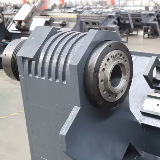
| Spindle | Runout test, speed range, bearing condition and warm-up procedure | The spindle defines rotational accuracy. |
| X/Z axis positioning | Positioning and repeatability report | Axis error becomes diameter and length error. |
| Turret indexing | Repeated index test on the same station and multiple stations | Tool return error changes dimensions. |
| Chuck and clamping | Chuck size, jaw type, clamping pressure and runout check | Workpiece movement defeats machine accuracy. |
| Tooling | Tool holder type, insert grade, overhang and center height | Weak tooling causes deflection and chatter. |
| Measurement | Caliper, micrometer, CMM or roundness tester, plus temperature | Inspection error can be mistaken for machine error. |
Define the acceptance method before the machine is built
A useful trial cut checks at least 5 repeated parts after warm-up, records the measured OD, ID, length, thread fit and surface finish, then compares the results against the drawing. HORISTAR’s published TCK configuration gives a measurable inspection starting point: 12-station servo power turret, ±50 mm Y-axis travel and TCK56Y spindle speed from 50 to 4500 rpm.
How the Turret Supports Smooth Cutting
A servo turret supports smooth cutting when it holds the tool in a stable position under load. Surface finish is not created by the servo motor itself; it is created by stable cutting contact between the insert and workpiece. Poor finish usually comes from one of these mechanisms:
- Tool overhang is too long: the insert flexes and creates chatter marks.
- Clamping is weak: the workpiece moves, especially during grooving or interrupted cuts.
- Feed and speed are mismatched: the tool rubs, burns or tears the material.
- Turret lock is unstable: the tool position shifts under load.
- Chip control is poor: chips scratch the surface or pack into grooves.
- Coolant is insufficient: heat raises tool wear and dimensional drift.
HORISTAR TCK Series: Model Selection Snapshot
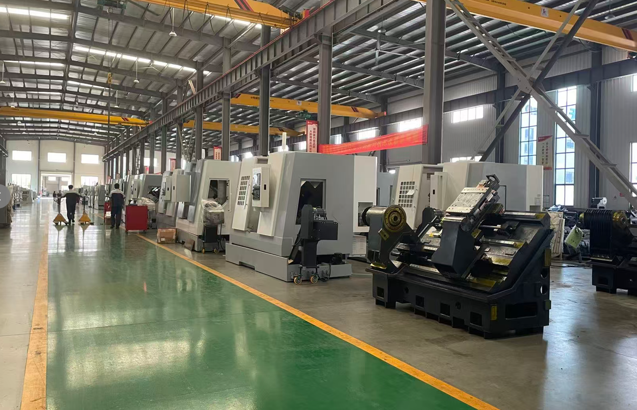
Use the largest part envelope first, then check bar work, operations and power. HORISTAR’s published TCK-series data gives the following selection starting point.
| Specification | TCK56Y | TCK63Y | TCK80Y |
|---|---|---|---|
| Swing over bed | 560 mm | 630 mm | 800 mm |
| Max. cutting diameter | 300 mm | 500 mm | 600 mm |
| Max. workpiece length | 500–1000 mm | 1000–3000 mm | 1000–3000 mm |
| Spindle bore | 65 mm | 80 mm | 80 mm |
| Spindle nose | A2-6 | A2-11 | A2-11 |
| Spindle speed | 50–4500 rpm | Up to 3000 rpm | Up to 3000 rpm |
| Standard chuck | 8″ hollow hydraulic | 10″ hollow hydraulic | 12″ hollow hydraulic |
| Turret | 12-station power | 12-station power | 12-station power |
| Main motor power | 15 kW | 18.5 kW | 18.5 / 37 kW |
TCK56Y fits smaller precision parts, higher-speed smaller-diameter work and bar capacity around the 65 mm spindle bore. TCK63Y is the middle frame for larger sleeves, fittings and medium shafts. TCK80Y fits the largest workpieces in the range and can be specified with higher motor power for heavier cuts.
Tool Station Count: How Many Stations Do You Need?
Choose turret station count by tool list, not by a generic “more is better” rule. A 12-station turret gives useful space when a job combines roughing, finishing and secondary operations. Example tool plan for a multi-operation shaft or connector:
Cycle Time Calculation: When Automation Pays Back
A servo turret pays back when it removes enough non-cutting time across repeated parts. Use your own measured tool-change time rather than a supplier’s best-case number.
Example Payback Calculation — 1,000-Piece Batch
Recalculate for your real data
If your part uses only 2 tools, redo the calculation; the payback may be too weak for turret automation alone. Formula: Time saved = tool changes × (manual change time − turret change time) × batch size.
Inspection and Ownership Planning
Plan inspection by cycle and ownership stage because turret issues often appear as gradual wear, not instant failure.
| Ownership Stage | Inspection Interval | What to Record | Buyer Action |
|---|---|---|---|
| Factory acceptance | 1 pre-shipment test | 5 repeated trial parts, OD/ID, thread fit and surface finish | Approve shipment only after the agreed report is complete. |
| First production month | Weekly for 4 weeks | First-part and last-part dimensions for the main job | Adjust offsets and process sheet before scaling volume. |
| Stable production | Every 6 months | Turret indexing, chuck runout, hydraulic pressure and axis backlash | Schedule preventive maintenance before defects rise. |
| Heavy batch production | Every 3 months | Tool station wear, locking sound, repeated OD drift and finish trend | Shorten inspection interval when output exceeds 2 shifts per day. |
| Annual review | Every 12 months | Service record, spare parts, accuracy trend and downtime hours | Decide whether tooling, chuck or turret service is needed. |
Acceptance Test Plan Before Shipment
A CNC lathe acceptance test should check structure, axis motion, spindle behavior, turret indexing, trial cutting, inspection data, safety and export documents before the machine leaves the factory. For overseas orders, pair this acceptance record with the importing CNC and laser machines from China workflow so payment, packing and document gates are checked before shipment.
| Test Area | Minimum Check | Accept / Reject Rule |
|---|---|---|
| Machine identity | Model, serial number, voltage and controller screen | Must match the order and invoice. |
| Spindle warm-up | Run through low, medium and high speed | No abnormal noise, vibration or alarm. |
| X/Z axis movement | Rapid traverse and feed movement | Smooth motion, no alarm, no visible hesitation. |
| Turret indexing | Index all 12 stations at least 3 cycles | No missed station, alarm or abnormal locking sound. |
| Turret lock | Cut after repeated indexing to the same tool | Dimension should stay within the agreed tolerance. |
| Chuck and hydraulics | Clamp/unclamp, pressure stability and jaw contact | Stable clamping, no visible leakage. |
| Trial cut | OD turning, facing, boring, grooving, threading if required | Results must match the agreed drawing checks. |
| Surface finish | Measure or compare the specified surface | Must meet the stated Ra or approved sample. |
| Safety | Door interlock, emergency stop and guards | Must function before packing. |
| Documentation | Manual, packing list, maintenance points and test record | Must be complete before shipment. |
Common Problems and How to Diagnose Them
Most “turret accuracy” complaints are actually system problems. Diagnose by symptom, then isolate the cause.
| Symptom | Likely Cause | What to Check First |
|---|---|---|
| OD size changes after tool change | Turret repeatability, tool offset error or thermal drift | Re-index same station 10 times and recut a light pass. |
| Chatter on finish pass | Tool overhang, insert grade, clamping, spindle speed or turret lock | Shorten overhang and run a conservative finishing cut. |
| Thread does not gauge | Tool center height, insert wear, pitch setting or spindle synchronization | Check tool setup and repeat thread on sample material. |
| Bore taper | Boring bar deflection, weak clamping or axis alignment | Reduce overhang and compare with a shorter boring bar. |
| Surface scratches | Chip control or coolant problem | Check chip evacuation and coolant direction. |
| Dimensions drift during long run | Heat, tool wear or clamping pressure change | Measure first 5 parts, middle-run parts and final 5 parts. |
RFQ Input List for a Servo Turret CNC Lathe
Send complete machining information instead of asking only for price. HORISTAR can recommend a more accurate TCK configuration when the inquiry includes real part data.
- Part drawing in PDF, DXF, STEP or clear photo with dimensions
- Material grade, hardness and blank type
- Maximum outside diameter and total length
- Bar diameter if the job uses bar stock
- Required tolerance for OD, ID, length, thread and groove
- Required surface finish, including Ra value if specified
- Operations required: turning, facing, boring, drilling, grooving, threading, chamfering, parting, milling or tapping
- Current cycle time and target output per shift
- Batch size per order and expected monthly volume
- Need for bar feeder, chip conveyor, parts catcher or robotic loading
- Local voltage, workshop temperature range and destination country
- Preferred acceptance test, sample material and inspection method
Get Engineering Support
Send your project requirements through Contact HORISTAR with the drawing, material and target output attached. The Service and After-Sales Support page explains the support path for buyers comparing overseas suppliers.
Specification Checklist
Use this checklist to compare offers from different suppliers.
| Specification | Why It Matters | Buyer Cut-Off |
|---|---|---|
| Maximum cutting diameter | Defines part envelope after chuck/tool clearance | Choose a machine with clearance beyond the largest drawing diameter. |
| Maximum workpiece length | Defines shaft and sleeve capacity | Include tailstock and chuck clearance. |
| Spindle bore | Defines bar stock capacity | Bar diameter must fit below bore and chuck limits. |
| Chuck size | Controls clamping range and rigidity | Match blank diameter and holding method. |
| Spindle speed and motor power | Affects cutting speed, torque and material range | Smaller parts benefit from higher rpm; heavy cuts need power. |
| Turret station count | Controls tool availability | Count real tools, then keep 1–2 spare positions if possible. |
| Tool interface | Affects rigidity and serviceability | Confirm holders available in your market. |
| Guideway and ball screw design | Affects motion stability and repeatability | Request axis accuracy or test data. |
| Control system | Affects programming and operator training | Choose a controller your team already supports. |
| Service package | Affects installation and uptime | Confirm manuals, training, remote support and spare parts. |
Frequently Asked Questions
A servo turret CNC lathe is a CNC turning machine with a servo-controlled tool turret that indexes multiple tools automatically during the machining cycle. It is used for parts that need repeated turning, facing, boring, grooving, threading, drilling or parting operations without manual tool changes between each step.
A servo turret CNC lathe improves repeatability when the turret indexes and locks tools consistently, but final accuracy depends on the full machine system. Bed rigidity, spindle runout, guideways, ball screws, chuck clamping, tool holders, thermal stability and inspection method all affect the measured result.
Choose turret station count by counting the tools needed for one complete part cycle. A simple part may need 3–5 stations, while a shaft, connector or fitting with roughing, finishing, drilling, grooving, threading and parting can use 8–10 stations. A 12-station turret leaves space for spare or special tools.
A servo turret is better when fast, repeatable programmed indexing is the priority, while a hydraulic turret can suit heavy-duty designs where hydraulic clamping and service are preferred. The better choice depends on locking rigidity, station count, tool load, maintenance access and the test result on your real part.
Before buying, define the largest part diameter and length, count the tools needed for one cycle, and require at least 5 repeated trial parts for precision jobs. For imported machines, request pre-shipment photos, videos, test reports, packing details and a clear acceptance checklist before final payment.
Send the part drawing, material grade, maximum diameter, length, bar size, tolerance, surface finish, operations, batch size, target output, automation needs and destination country. These details let HORISTAR recommend the TCK model, chuck, turret/tooling configuration, sample test plan and export support.
Review Record
This article was reviewed by the HORISTAR CNC application team on 2026-06-22 for product fit, buyer selection logic, RFQ completeness and consistency with HORISTAR’s published CNC lathe information.
References
- HORISTAR CNC Lathe Machine page — horistartech.com/cnc-machine/cnc-lathe-machine/
- HORISTAR Contact and Service pages — horistartech.com/contact-us/
- ISO 230-2:2014, Test code for machine tools — Part 2: Determination of accuracy and repeatability of positioning of numerically controlled axes
- ISO 13041-1:2020, Test conditions for numerically controlled turning machines and turning centres
- ISO 23125:2015, Machine tools — Safety — Turning machines
- ISO 21920-3:2021, Geometrical product specifications (GPS) — Surface texture: Profile