Robotic Welding Seam Finding and Tracking: Touch Sensing, Through-Arc or Laser?
Choose a sensing system by identifying when the weld joint moves and what the welding process allows. If loading variation moves the joint outside the validated path tolerance, pre-weld seam finding may provide the required correction. A joint whose position changes along the weld may need tracking during welding. Some applications need both.
That distinction matters when specifying a CNC robot welding machine. A system that locates the start of a seam has not necessarily proved that it can follow the complete joint. Equally, a tracker that works during welding may still need a separate method to find a reliable starting position.
The useful purchasing question is: what variation must this cell detect, correct and verify on our actual parts? Answer that before comparing sensor brands or advertised accuracy.

Establish what is moving
Start with the joint in its production fixture. Record its position before clamping, after clamping and after any preceding welds. This separates several problems that can look like the same missed seam.
| Observed pattern | Question to investigate | Direction for the sensing review |
|---|---|---|
| The entire assembly shifts between loads | Are the locating surfaces and loading method repeatable? | Correct unstable seating first; then evaluate a pre-weld position correction for the remaining variation. |
| The start position is repeatable, but the joint curves away later | Does the real seam differ from the taught path? | Evaluate multiple search points, a pre-scan or tracking along the joint. |
| The joint moves after an earlier weld | Is the movement predictable and within the approved process window? | Include the production weld sequence in the trial. |
| Gap or edge mismatch changes although the seam center is found | Can the welding procedure accommodate that joint condition? | Treat joint location and weld-process suitability as separate acceptance questions. |
These are investigation routes, not diagnoses from a photograph. A locating error can coexist with thermal movement, and both can coexist with an unsuitable joint gap.
A stable fixture and a proven program may already meet the requirement without additional sensing. If a representative baseline passes across the expected variation range, document that result. Add sensing to address an identified limitation rather than assuming every cell needs it.
If the part rocks before clamping or springs away when released, work through the fixture inspection and datum checks first. A sensor correction should not conceal a fixture that cannot return the assembly to its intended position.
Specify the correction the joint actually needs
Before choosing hardware, define what the controller must correct. A rigid assembly can translate in three directions and rotate about three axes. A fixture may constrain most of those movements, leaving only one or two that matter. A flexible assembly adds local shape changes that cannot be represented by one rigid position shift.
This distinction determines the search pattern. A contact with a flat surface establishes a position along the search direction; it does not independently reveal every component of the assembly’s pose. Extra touches help only when their directions and spacing provide new geometric information. Several touches on essentially the same feature can repeat the same information while adding cycle time.
Why a correct start point can still produce a missed seam
Consider an illustrative straight seam 1,000 mm long. Its measured lateral displacement from the taught path is +1.0 mm at the start and +3.0 mm at the end. Suppose the part is rigid and the change is linear.
The required correction at distance x, in millimeters, is:
Lateral correction = 1.0 + (3.0 − 1.0) × x ÷ 1,000.
A single +1.0 mm translation fixes the start but leaves a 2.0 mm residual error at the end. A correction that accounts for the seam’s changed direction can address this rigid alignment error. Whether a particular controller supports that transformation must be confirmed; two detected points are not a complete six-axis pose measurement.
Now suppose both ends are correctly located but the middle bows by 2.0 mm. An endpoint alignment cannot reveal that bow. Intermediate measurements or tracking are needed if the bow exceeds the validated weld-path allowance. If the bow develops only after the preceding weld, a scan made before that weld may already be obsolete.
The practical specification should therefore name the required correction: translation, rigid rotation, local path shape, torch orientation, or some combination. “Automatic seam correction” is too broad to establish any of these.
What each method actually provides
Touch sensing: finding the part before welding
In a typical electrical wire-touch arrangement, contact between the wire and the workpiece closes a sensing circuit. The controller uses detected positions to establish an offset before executing the weld path. Yaskawa’s touch-sensing interface example illustrates why the required interface must be checked against the actual power source.
The practical attraction is a direct reference to the loaded part. The tradeoff is the search motion added to the cycle and the need for reliable contact.
Surface condition matters. Yaskawa identifies mill scale, dirt and oil among the causes of missed touch detections in its touch-sense troubleshooting guidance. Its WireSense application discussion also describes difficulties with thin lap or butt joints and the slower searches that can be needed with soft welding wire.
Ask which surfaces the cell will search, which directions it will measure and how long the complete search takes. Finding one point does not establish every translation or rotation that a complex assembly may require.
Through-arc tracking: following a suitable joint during arc welding
Through-arc systems infer joint position from electrical behavior during welding. For example, Yaskawa’s ComArc documentation describes current feedback, a weaving motion and joint geometry that changes electrical stick-out. It specifies fillet joints and suitable unfilled grooves, with restrictions on fully filled grooves.
Those requirements make compatibility more specific than “the machine has MIG welding.” The proposed power source, transfer mode, joint geometry and permitted torch motion must work with the selected tracking implementation.
Different implementations also use different signals. ABB’s Weldguide IV datasheet explains that current regulation in modern power sources can make current measured at the source insufficient as the sole tracking input. Its approach combines external current sensing with arc-voltage sensing nearer the arc. ABB describes compatibility with several welding modes for that system. This supports checking the complete power-source, sensor and controller combination; it does not establish that all through-arc systems behave alike.
A laser-only weld supplies no welding arc for a through-arc system to monitor. For an arc-welding project, ask the integrator to demonstrate tracking using the proposed production process rather than a convenient demonstration weld.
Check correction rate as well as correction range
ComArc’s setup note states a default correction of 0.100–0.150 mm per weave cycle. Its setup guidance calls for an initial test weld at least 8 inches long, a weave amplitude of at least 2.5 mm, and phase-compensation and sensing tests. These are requirements of that documented implementation, not settings to transfer to another tracker.
ABB’s Weldguide IV datasheet instead specifies a minimum weave width of 1.5 times wire diameter: 1.8 mm for 1.2 mm wire. Confirm how each controller defines amplitude or width before comparing its settings.
For a screening calculation, suppose the configured correction allowance is 0.10–0.15 mm per cycle and weaving occurs at 2 cycles per second. The resulting command allowance is 0.10 × 2 = 0.20 mm/s to 0.15 × 2 = 0.30 mm/s. This is a simplified rate budget; it is not a measured maximum tracking speed or a manufacturer’s accuracy guarantee.
At an assumed travel speed of 6 mm/s, the lateral rate needed to follow a linear ramp is travel speed × lateral change ÷ ramp length:
| Assumed linear change in joint position | Required lateral rate | What the rate comparison establishes |
|---|---|---|
| 2.0 mm over 1,000 mm | 0.012 mm/s | Below the assumed command allowance; detection and dynamic response still need testing. |
| 2.0 mm over 100 mm | 0.12 mm/s | Also below that allowance, with less margin. |
| 1.5 mm over 20 mm | 0.45 mm/s | Above the assumed allowance; this configuration cannot follow the ramp exactly under the model. |
A bow does not generally have a constant slope, and an abrupt step is not a 20 mm ramp. For those geometries, evaluate the steepest relevant local slope and the controller’s transient behavior. Filtering, latency, signal quality and starting error can cause failure even when the average rate appears adequate.
If a trial fails, compare detected seam position, requested correction and executed correction. That separates an unavailable or wrong measurement from a correction the controller could not follow. Yaskawa identifies correction amount as one setup variable; any integrator-approved change needs the difficult condition and the nominal reference retested. Raising that setting alone does not repair poor detection.
Optical laser sensing: measuring the joint without contact
A laser profile sensor can measure joint geometry and send position information to the robot controller. Scansonic describes this approach in its TH6D-Advanced optical tracking sensor, which measures features such as the gap, edge offset and tool position relative to the workpiece.
Confirm whether the quoted package performs a pre-weld search, an ahead-of-process scan, continuous tracking or a combination. “Laser vision” alone does not define the delivered function.
Physical access and optical response are part of the decision. A sensor near the torch occupies space, and reflective surfaces can challenge some optical searches. Yaskawa discusses both issues in its WireSense application note. A clean, open demonstration joint therefore provides limited evidence for a reflective production assembly with clamps close to the seam.
Also distinguish a profile sensor from an ordinary 2D camera. Yaskawa’s MotoSight 2D welding example explains that lateral detection alone may need an additional method to resolve height variation.
Read resolution, working range and interface rate separately
Scansonic’s TH6D-Advanced page specifies three measuring lines and 25 µm resolution at the TCP. It lists a 150 mm working distance, a 50 mm Y range at nominal Z and a 60 mm Z range at nominal Y. It also gives a +10°C to +45°C operating range, laser class 3B and IP64 with connectors plugged in. These are specifications of that sensor, not a statement of HORISTAR’s supplied configuration.
Resolution does not bound joint-detection error or the final torch-path error. Working ranges are tied to the stated measurement plane; do not treat one lateral-range figure as a constant field of view at every distance. Temperature and connector conditions belong in the installation review. The sensor’s laser classification must also be addressed in the integrated cell’s safety assessment; it is separate from the welding laser’s classification.
Line count alone does not select a winner. In its single-line versus three-line discussion, ABICOR BINZEL describes constraints involving small components and the robot interface’s use of additional data. It markets a single-line sensor, so treat the comparison as a supplier’s application argument. Request joint-specific evidence from each proposed system, including which position and orientation information reaches the controller.
For an illustrative interface, assume accepted measurements arrive at 15 or 20 Hz. At 6 mm/s, the path distance between new measurements is 0.40 or 0.30 mm. At 100 mm/s, it is about 6.67 or 5.00 mm. These assumed rates are not universal robot-interface limits.
The calculation is distance between measurements = travel speed ÷ accepted measurement rate. It does not describe every servo correction: the controller may buffer, filter and interpolate between measurements. Ask for the actual delivered measurement rate, latency, timestamps, interpolation and behavior after missing data. A sensor’s camera frame rate does not answer those questions.
Compare options against the same production problem
| Decision factor | Electrical touch sensing | Through-arc tracking | Optical laser sensing |
|---|---|---|---|
| Main function to specify | Search and locate before welding | Correct position during compatible arc welding | Search, profile measurement or in-process tracking, depending on integration |
| Evidence needed | Reliable detections on production surfaces | Stable tracking with the actual arc process and joint | Reliable geometry detection on the actual surfaces and joint access |
| Cycle-time question | How much time do all search moves add? | Does the required weld motion fit the approved procedure? | How much scanning, approach and processing time is added? |
| Important limitation | Contact quality and search accessibility | Process, signal and joint-shape compatibility | Optical visibility, surface response and sensor clearance |
| What the purchase trial must prove | Correct path offset after loading variation | The weld follows the real joint throughout the tracked segment | Detection and correction remain reliable in the complete fixture |
This table is a screening aid. It does not establish that every robot controller supports every method, or that an option is included in a base machine quotation.
Before accepting a method, ask for its documented limits for the actual joint: minimum detectable step or gap, allowed surface condition, search envelope, smallest qualified seam radius and torch clearance. A tightly closed butt joint needs a detectable feature; a thickness threshold from one sensor and search strategy cannot be applied to all systems. Use the OEM conditions above to set trial questions, then test the proposed hardware and software on the production joint.
Count the entire search in the cycle
Time approach, detection, retract, wire preparation and any retry. In an illustrative pattern, four joints each need two touches and each complete touch takes 4 seconds:
Search time = 4 × 2 × 4 = 32 seconds per part.
If the baseline cycle takes 180 seconds excluding search, the new cycle takes 212 seconds, a 17.8% increase. Across 2,000 parts, search occupies about 17.8 cell hours. Those figures assume the search cannot overlap other work and needs no additional retries.
Compare that measured time and attendance with an optical alternative’s complete search cycle, integration cost and access requirements. A shorter search has economic value only when its saved capacity or attendance can be used. The companion article, Robotic Welding for Small Batches: Programming, Changeover and Batch-Size Economics, carries this 32-second example through the time and cost crossovers.
Verify calibration and total path error
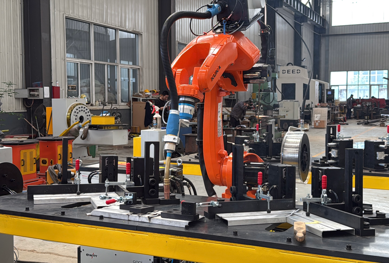
Check the complete chain from measurement to torch position
A sensor measures in its own coordinate system. The controller must relate that measurement to the robot, tool and workpiece frames, then execute a corrected path. A repeatable sensor can therefore produce a repeatable wrong weld if the tool or frame calibration is wrong.
Yaskawa’s robot-to-station calibration guidance requires accurate tool-center-point data before establishing the relationship between the robot and a coordinated station. That requirement matters when a demonstration includes a positioner: a successful trial at one table angle does not establish correct behavior at the others.
Use a reference joint whose position has been measured independently. Have the integrator compare the reported joint location and the resulting tool location at representative torch orientations and positioner angles. Repeating one search without changing the setup tests short-term repeatability. Changing orientation or station angle tests additional parts of the coordinate transformation.
Do not use the robot’s own corrected coordinates as the only reference for proving that correction. That can hide an error shared by the measurement and the reported result.
Separate repeatability from accuracy
ISO 9283 treats pose accuracy, pose repeatability and path performance as distinct robot characteristics. A tight cluster of repeated positions can still be displaced from the commanded position. Repeatedly returning to a taught point therefore does not establish accuracy at every CAD-generated point or along a corrected moving path.
Ask which characteristics were tested, at what payload, speed, poses and work envelope. Include the installed torch and any positioner where they affect the application. Offline-generated paths need the real coordinate transformations verified, and sensor-generated corrections need their execution checked over the required distance. Do not enter catalogue pose repeatability as the path-execution bound without evidence that supports that substitution.
Turn an accuracy claim into an error budget
The following is a conservative illustrative allocation, not a sensor specification or welding tolerance. Assume process trials have established a maximum permissible lateral path error of 0.50 mm for this joint.
| Contribution in the same lateral direction | Assumed bounded error |
|---|---|
| Joint detection | 0.10 mm |
| Tool-center-point error | 0.12 mm |
| Sensor/workpiece frame transformation | 0.08 mm |
| Path execution and interpolation | 0.10 mm |
| Joint movement after it was measured | 0.15 mm |
| Conservative sum | 0.55 mm |
Even a 0.10 mm sensor contribution does not make this 0.50 mm application acceptable: the proposed total reaches 0.55 mm. The design needs smaller contributions or evidence from the integrated cell that supports a different, valid model.
This addition assumes non-overlapping error bounds acting in the unfavorable direction. Do not add terms that already include each other. Do not replace the sum with a root-sum-square calculation unless the error definitions, distributions and correlations justify it. A brochure resolution value is also not a measured detection-error bound.
Allocate and test height and angle errors separately where they affect the approved weld. A lateral budget cannot establish acceptable contact-tip distance or torch angle.
Laser welding needs a separately qualified allowance
TWI’s laser-weld fit-up guidance describes typical butt-joint gaps below 10% of material thickness and the importance of clamping for thin-sheet autogenous welding. For 1.5 mm sheet, 10% is 0.15 mm. This is a fit-up screening figure, not a guaranteed acceptable gap for every material and process.
Joint gap and lateral beam-placement error are different quantities. A 0.15 mm gap limit cannot be copied into the torch-position budget. Suppose separate process trials establish an illustrative ±0.10 mm lateral allowance. The earlier 0.55 mm conservative bound would exceed that magnitude by a factor of 5.5, requiring a different allocation and verified integrated performance. The original 0.50 mm example was not a generic arc-welding tolerance either.
Beam wobbling can be part of a qualified response to gap variation. A 2024 study by Boldrin and colleagues combined vision-based robot-path correction with gap-dependent circular wobbling in tests on 2 mm AISI 301 stainless sheet. That is evidence for the studied configuration, not a transferable gap guarantee. Qualify the intended material, gap, beam path, speed and weld result together before accepting wobble as a solution.
Keep sensing acceptance separate from weld acceptance
A system can successfully follow the joint while producing an unacceptable weld. Finding the centerline does not itself establish penetration, fusion, acceptable porosity or final assembly dimensions.
Evaluate two linked results:
- Sensing performance: did the system detect the intended feature, apply the correct offset and remain within its configured correction range?
- Welding performance: did the resulting joint meet the agreed drawing, welding procedure and inspection requirements?
Likewise, gap measurement is not automatically adaptive gap control. If the supplier proposes changing welding parameters in response to a measured gap, request the supported adjustment range and the process evidence for that function.
This avoids buying a tracker to solve variation that actually requires better fit-up, a different joint design or a revised welding procedure.
Check whether the correction arrives at the right place and time
Continuous tracking is a control problem as well as a detection problem. Ask how the system matches each measurement to its position along the path, how it filters the signal, and what correction speed and range it can execute.
For a sensor mounted ahead of the weld, measurement age matters. In an illustrative constant-speed case, a 30 mm distance along the path between measurement and welding at 6 mm/s creates a 5-second interval. If that exact joint location moves laterally at an assumed 0.08 mm/s during the interval, its position changes by 0.40 mm before welding reaches it. These are explanatory assumptions, not TH6D or HORISTAR specifications.
The calculation is 30 ÷ 6 = 5 seconds, followed by 5 × 0.08 = 0.40 mm. It shows why a precise pre-scan can still be unsuitable for a joint that continues to move. The relevant distance follows the actual path; a straight-line sensor offset is not automatically the correct value on a curved seam.
Data timing creates another question. At 6 mm/s, an unaccounted 0.05-second timing difference corresponds to 0.30 mm of along-path registration. That is not automatically 0.30 mm of lateral weld error. The lateral consequence depends on how rapidly the joint shape changes there. The integrator should demonstrate timestamping, path buffering and controller synchronization rather than interpreting sensor update rate as finished-weld accuracy.
For through-arc tracking, ask how any signal filtering trades noise rejection against response delay. More aggressive correction is not automatically better: the welding process and joint geometry must produce a useful signal. Ask for results through the actual starts, ends, changes of direction and tack locations, rather than only the middle of a uniform fillet.
Multi-pass work needs particular attention. The measured feature and electrical response can change after earlier passes fill the groove. The ComArc restrictions discussed above are one reason to qualify tracking on the relevant pass, not extrapolate from the open root geometry.
Diagnose failures by separating detection from execution
The following routes are engineering checks, not automatic diagnoses. Run them through the integrator’s safeguarded test procedure and preserve the original data before changing settings.
| Observed result | Discriminating check | Interpretation and next action |
|---|---|---|
| Search occasionally reports no joint | Compare saved raw detections on clean and normal production surfaces at the same position | If detection changes with surface condition, investigate the sensing interface or optical/contact conditions before adjusting the robot path. |
| Search returns a plausible but wrong feature | Compare the selected feature with an independent reference and the expected search region | A valid signal may describe a plate edge, tack or clamp. Correct the feature definition and search limits; repeated detection alone does not prove correctness. |
| Correct detected feature, constant offset at the torch | Compare sensor coordinates, transformed coordinates and independently measured tool position | Localize the error to calibration, active tool/frame or the applied offset; do not compensate it by deliberately teaching the wrong seam. |
| Error changes with torch orientation or table angle | Repeat the reference test across those poses | Review the tool and station transformations before increasing tracking sensitivity. |
| Cold path check passes, welding departs from the seam | Compare the joint before and during the production weld sequence and examine tracking data | Distinguish movement after measurement from arc-signal or optical deterioration during welding. |
| Failure occurs at a tack, interruption or end | Inspect the feature actually available at that location and the configured invalid-data response | Qualify a supported search/tracking transition or reject the condition. Do not accept an undocumented continuation using stale data. |
Once the cause is corrected, reproduce the failed condition and rerun the nominal reference. Otherwise, an improvement on one difficult joint may have introduced an error on ordinary production parts.
Build a representative sensing trial
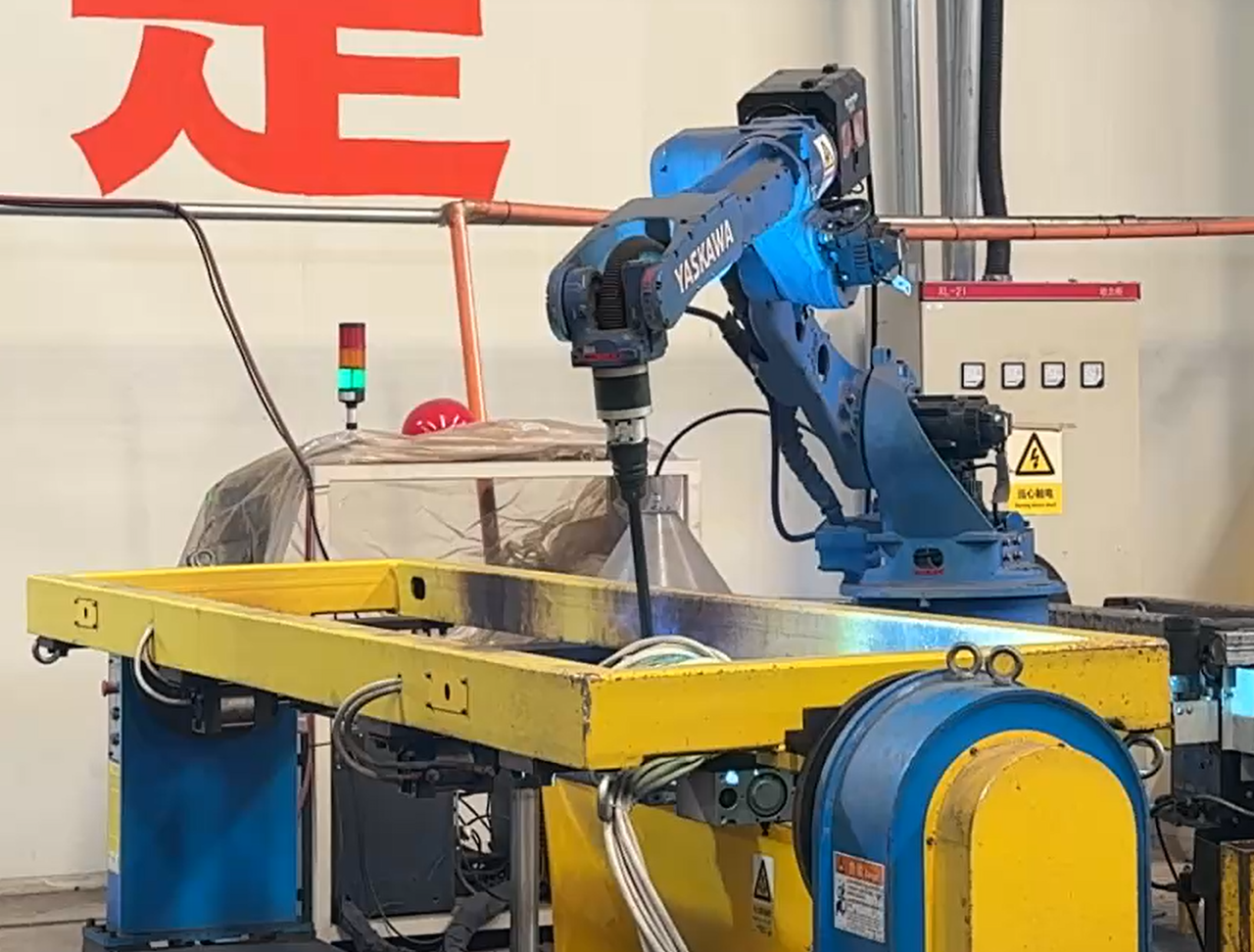
First establish a nominal baseline with the agreed material, joint, fixture and welding procedure. Record the sensor setup, robot program and inspection method so that subsequent trials can be compared with it.
Then ask the integrator to run a bounded variation trial using its approved safeguarded procedure. Use variations measured from production, together with agreed boundary conditions. Keep artificial offsets within the validated mechanical and process limits.
| Trial condition | Record | What it establishes |
|---|---|---|
| Nominal part, repeated unloading and reloading | Search result, path correction, weld result and complete cycle time | Whether the baseline is repeatable |
| Representative location changes | Direction and size of each change, applied correction and result | Whether the required directions are detected correctly |
| Representative seam-shape variation | Joint profile and result along the complete weld | Whether a start-point correction is sufficient |
| Production surface condition | Material condition and detection success or failure | Whether a clean sample concealed a sensing limitation |
| Actual clamp and torch arrangement | Clearance through approach, welding and exit | Whether the sensor fits the production cell |
| An agreed unreadable or out-of-range condition | Fault response and controlled recovery | Whether invalid data produces the intended system response |
Do not quietly remove unsuccessful trials from the report. Identify whether the cause was detection, controller integration, path execution or the welding process. After a correction, repeat the affected condition and a nominal baseline.
A recorded sensor offset is useful evidence, but it is not a substitute for inspecting the resulting weld.
Make the trial report expose unsuccessful automatic cycles. For each attempt, retain the part ID, measured variation, detection result, requested correction, actual path residual, weld disposition, cycle time and any manual intervention. Report automatic completion separately from completion after an operator retries or reteaches the job.
Use independent path measurements at the start, at meaningful changes in geometry and near the end. An average signed error can conceal opposite errors on the two sides of the seam; report the relevant maximum absolute residual as well as the pattern along the path. Agree the sample coverage and permissible residuals from the welding requirement, not from the best results seen during the demonstration.
Prepare a sensing specification for your enquiry
Use the following fields when discussing a HORISTAR robot welding machine:
| Field | Information to supply or confirm |
|---|---|
| Joint and process | Drawing revision, material, thickness, joint type and intended welding process |
| Variation | Measured location, orientation, gap and edge-mismatch ranges |
| Timing | Whether variation exists before welding or develops during the sequence |
| Access | Fixture model, clamp locations and torch approach constraints |
| Cell integration | Robot, controller, power source, sensor, interface and software options |
| Acceptance | Weld inspection criteria, allowed cycle time and required evidence |
| Recovery | Required behavior after failed detection or an out-of-range correction |
Include representative production parts and photographs of their normal surface condition. Ask HORISTAR to confirm the available configuration against these inputs. A defined variation range and a relevant trial will make that discussion more useful than a request for the “most accurate” sensor.