Refractometer coolant control is a maintenance method that combines the optical reading, product factor and contamination check.
Tramp oil, fines or poor mixing distort the result when contamination blurs the boundary.
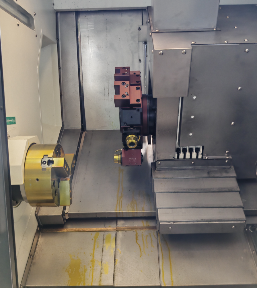
Use the coolant supplier’s limits on a HORISTAR CNC lathe machine or any comparable platform. Measure, diagnose, correct, circulate and recheck.
CNC Lathe Coolant Process and Quality Control
Use one loop for each sump or central system.
Oil shifts the reading because it refracts light. Fines blur the line because they scatter light. Premixing limits local error because both components enter together.
Calibrate and Sample Before Changing CNC Lathe Coolant
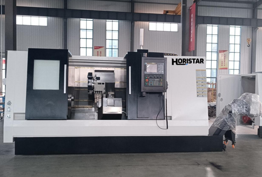
Zero the instrument with clean water, then sample circulating working fluid below any surface oil.
Use this routine:
- Zero: use the supplier’s specified clean water.
- Clean: remove oil and dried emulsion from the prism.
- Sample: avoid the surface film and stagnant corners.
- Settle: avoid bubbles on the prism.
- Read: record whether the boundary is sharp or diffuse.
- Calculate: apply the product-specific factor.
- Log: keep the raw reading and result.
Do not copy a factor from another coolant. Update the work instruction when the product changes.
Worked CNC Lathe Concentration Calculation
For the field example, actual concentration equals raw reading multiplied by the product factor.
| Reference configuration | Published value | Decision it supports |
|---|---|---|
| System volume | 200 L (52.8 US gal) | Sets the planning basis |
| Raw reading | 4.1 °Brix | Keep the optical result |
| Product factor | 1.4 | Use the product-specific value |
| Calculated concentration | 4.1 × 1.4 = 5.74% | Supports diagnosis |
| Volume calculation | 200 × 0.0574 = 11.48 L | Shows the concentration-equivalent amount |
| Decision boundary | Supplier instructions | Do not dose from arithmetic alone |
The calculation supports a maintenance decision, not direct dosing.
Contamination Checks Before CNC Lathe Coolant Dosing
A clear line does not prove a clean sump. Oil changes refraction, while fines scatter light and blur the boundary.
| Refractometer observation | What it may indicate | Next action |
|---|---|---|
| Sharp boundary | Stable optical sample | Record and compare with the product range |
| Diffuse boundary | Oil, fines or poor sampling | Clean and resample |
| Upward trend | Evaporation or oil interference | Inspect makeup and contamination |
| Downward trend | Drag-out, leaks or excess water | Audit the top-up method |
| Step change after cleaning | Cleaner or incomplete rinse | Review the cleaning record |
Control CNC Lathe Tramp Oil by Physical Form
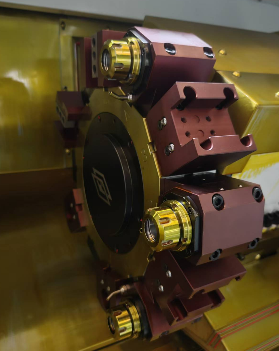
Match the removal method to free, dispersed or emulsified oil.
Free-floating oil: remove it before it circulates
Use a suitable skimmer or removal method before surface oil returns to the pump. Trace way, hydraulic or spindle-oil entry.
Dispersed oil: give separation equipment time to work
Let the system settle or use suitable separation equipment before sampling.
Emulsified oil: do not destroy a good emulsion by guessing
Escalate emulsified oil to the coolant supplier and follow the approved clean-out and disposal procedure.
Match CNC Lathe Filtration to the Process
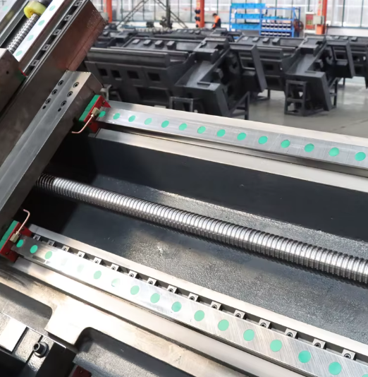
Fines return to the cutting zone when filtration does not capture them. This affects tool life, finish and sample quality.
| Filtration question | If the answer is “yes” | Control implication |
|---|---|---|
| Do fines affect finish? | Particles return to the cut | Improve capture and verify flow |
| Is sludge collecting? | Solids settle in the tank | Clean the tank and return path |
| Does pump flow fall? | The filter is loaded | Service the filter |
| Is the system central? | Loads come from several machines | Size for the combined load |
| Is coolant high-pressure? | Flow demand is higher | Verify filter capacity |
At 25 µm (0.0010 in), the field circuit captured finer contamination than at 50 µm (0.0020 in). Concentrate is not a filter.
Premix CNC Lathe Coolant Before Top-Up
Follow the product instructions and prepare makeup fluid before adding it to the sump.
Use a repeatable work instruction:
- identify the product and target;
- verify the water source;
- measure the water volume;
- mix in the specified order;
- label product, ratio, date and operator;
- add the prepared fluid;
- circulate and resample;
- record the reading, factor and action.
CNC Lathe Coolant Process and Quality Log
Use a 7-day interval for an individual sump and a 1-day interval for a central system when the supplier permits.
| Log field | Why it matters |
|---|---|
| Date, time and machine | Locates the trend |
| Raw reading and factor | Preserves the calculation |
| Calculated concentration | Shows the working level |
| pH result | Adds fluid condition |
| Sump and makeup volume | Shows water or fluid movement |
| Tramp-oil observation | Explains diffuse readings |
| Filter condition | Connects fines to delivery |
| Odor, foam or finish change | Adds the production symptom |
Read the trend with pH, oil and filter condition instead of using one percentage alone.
Failure Signals Before Changing CNC Lathe Coolant
| Production symptom | Likely coolant-control mechanisms | First check |
|---|---|---|
| Tool life falls | Oil, fines, delivery or pH | Inspect sample and filter |
| Corrosion appears | Fluid, water or pH condition | Verify concentration and pH |
| Foam increases | Water, air or mixing | Review the makeup sequence |
| Odor returns | Contamination or stagnant zones | Inspect and clean the sump |
| Boundary is diffuse | Oil, fines or dirty prism | Clean and resample |
| Pump flow drops | Filter loading or sludge | Inspect the filter and return |
Match the correction to the mechanism. Concentrate is not a filter.
HORISTAR CNC Lathe Field Record
In July 2026, HORISTAR reviewed semi-synthetic coolant on TCK-series lathes at an anonymized Southeast Asian hydraulic-parts plant.
Initial effective filtration measured 50 µm (0.0020 in); the final control was 25 µm (0.0010 in).
The factor was 1.4. A 4.1 °Brix reading equaled 5.74%. Initial pH was 8.4, and the continuous oil layer measured 3–5 mm (0.12–0.20 in).
The team zeroed, resampled, removed oil and sludge, improved filtration and premixed makeup fluid.
| Control/result | Before correction | After correction |
|---|---|---|
| Raw refractometer reading | 4.1 °Brix | 5.0 °Brix |
| Product factor | 1.4 | 1.4 |
| Calculated concentration | 5.7% | 7.0%; held at 6.8–7.2% |
| pH | 8.4 | 8.9–9.1 |
| Effective finishing-circuit filtration | 50 μm | 25 μm |
| Finishing-insert life | 165 parts/edge | 198 parts/edge |
| Sampled surface-quality nonconformance | 5.8% | 2.6% |
After 2 weeks, insert life moved from 165 to 198 parts/edge, nonconformance from 5.8% to 2.6%, and daily concentrate use was 15–18% lower. The result belongs to the complete control loop.
Checks used a 0–20 °Brix refractometer, pH tools, filter records, dimensional tools and a roughness instrument.
Source: HORISTAR July 2026 internal project record, verified by Doris Li, CNC Application Engineer, HORISTAR CNC Application Team. The customer identity remains confidential.
When One Coolant Number Is Not Enough
Escalate conflicting or persistently diffuse readings to the coolant supplier or a laboratory.
Use the product’s own factor and test instructions for any alternate method.
Do not choose a single-number coolant policy
Do not apply one percentage to every machine. Compare lifecycle cost through fluid, filters, cleaning, tool life and downtime.
Escalate when:
- oil is visible or the reading is diffuse;
- the fluid was cleaned or changed;
- sludge is heavy or the filter bypasses;
- pH, odor or corrosion conflicts with the reading;
- a central system combines different demands.
Use a diagnostic plan, not a larger dose.
CNC lathe coolant specification checklist and RFQ inputs
Send:
- machine model and tank volume;
- coolant product, ratio and data sheet;
- water source;
- refractometer model and factor;
- dated readings and calculations;
- pH and visible symptoms;
- sump and filter photos;
- material and cutting operation;
- filter type and service state;
- the production symptom.
Request engineering support. See the accuracy guide and shipment checklist.
Need a coolant & process review for your CNC lathe?
Send the sump data, machine model and production symptom.
Frequently asked questions
What interval should be used for CNC lathe coolant concentration checks?
Use the coolant supplier’s interval. Shorten it for an unstable trend, small sump or heavy contamination because fast changes need earlier action. Record the reading, factor and pH together. Include oil and filter condition so the next decision uses the full condition.
Can I use the same refractometer factor for different coolants?
No. The factor is product-specific. Record the raw reading and factor together. Update the work instruction when the fluid changes. An old factor applied to a new product gives the wrong calculated concentration and triggers the wrong makeup decision.
Why is my CNC lathe refractometer reading high after tramp oil enters the sump?
Oil also refracts light. Under heavy contamination, it raises the apparent reading and blurs the boundary. Clean the prism, sample below surface oil and inspect the sump before changing the ratio. Let the sample settle when needed, then log the result for repeatable decisions.
Should makeup fluid be mixed before it enters the CNC lathe sump?
Yes, when the selected coolant instructions require premixing. Combine water and concentrate in the specified order. Label the batch, add it through the correct point, allow circulation and resample. This reduces local concentration errors and makes the correction record repeatable.
Is a belt skimmer enough for every CNC lathe tramp-oil problem?
No. A skimmer removes free-floating oil, not every contamination form. Dispersed or emulsified oil requires a method matched to the selected fluid and system. Identify the oil source, allow separation when appropriate, and follow the supplier’s clean-out procedure before changing concentration.
What does filtration change in CNC lathe coolant control?
Filtration controls the fines that affect delivery, finish, tool life and sample quality. A loaded or bypassing filter creates symptoms that concentration changes cannot correct. Inspect actual flow, filter loading and return-path contamination before increasing coolant strength or changing the product.
Reference documents
- ISO 6743-7:1986 — metalworking-fluid family classification
- ASTM D2881-19(2025) — metalworking-fluid terminology
- ASTM E1497-17 — selection and safe use
- Blaser Swisslube — coolant handling guidance
- Blaser Swisslube — measuring coolant concentration
Reference note: These references identify the fluid category, terminology and safe-use framework for an RFQ. The HORISTAR values are project-specific; confirm product limits, factor and handling instructions with the selected coolant supplier.