Press Brake Bend Sequence Planning for Box Parts: Clearance, Gauging and Part Removal
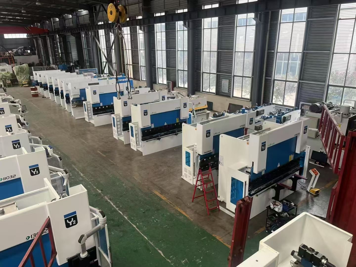
A workable box-bending sequence must do more than reach the final angles. At every stage, the part must fit the machine, reach a reliable gauging position, remain clear through the forming motion and leave the tooling after the bend.
Start with the finished part and the actual machine-and-tooling envelope. Then compare candidate sequences through every intermediate shape. Rules such as bending short flanges first are only candidate-generation aids; release requires a clear full-motion path, usable gauge contact and a demonstrated removal path for the exact setup.
This guide is a planning and quotation-analysis method for trained manufacturing personnel. It is not a machine operating procedure or a substitute for the manufacturer’s safeguarding and setup instructions.
Why an Apparently Simple Box Can Be Difficult
As walls are formed, they occupy space that was open when the blank was flat. Opposing walls and inward returns restrict access when their swept envelope intersects the punch, holder or removal path. Approved Sheet Metal’s deep forming guidance describes these progressive access problems.
This creates a useful planning distinction: a bend that clears on its own still fails after another bend if the new intermediate shape blocks the tool or gauge. Reviewing isolated bend lines is therefore insufficient.
A sequence should be treated as a set of intermediate states. Each state needs an answer to four questions:
- Does the part load and reach the required position without entering a prohibited area?
- Does the intended reference contact the gauge at the specified datum?
- Is the complete forming motion clear?
- Does the documented withdrawal or reorientation path remain clear for the next operation?
Assemble the Geometry Required for Analysis
Use the released drawing and a consistent model revision. Include material, thickness, bend radii, bend direction, flange dimensions, relief details and the dimensions that control fit with the mating assembly.
The machine model must represent more than the punch tip and die opening. Tooling supplier WILA identifies collision risks involving the part, tooling, clamping, machine structure and backgauge. Its guidance also distinguishes available opening from the space consumed by the installed tool stack. WILA: strategies for avoiding part collisions.
Before approving a sequence, obtain the actual profiles and relevant limits for:
| Review input | What must be represented |
|---|---|
| Upper tooling | Punch profile, working height, holder and clamp geometry |
| Lower tooling | Die profile, opening, height and mounting arrangement |
| Machine envelope | Open height, available stroke, throat and relevant structural obstructions |
| Gauging | Finger geometry, available axes, travel and intended contact features |
| Part handling | Supports and the space needed to load, rotate and remove the part |
| Tool configuration | Segment lengths, gaps and the installed configuration used for the simulation |
A nominally similar punch is not an adequate stand-in when a small profile difference controls clearance. Keep the tool drawing revision with the reviewed sequence.
Label Bends Before Comparing Orders
The feature map below assigns identities to four walls around a base. It deliberately omits dimensions, bend allowances and detailed corner reliefs. The letters identify features; they do not prescribe a bend order or define a manufacturing blank.
| Feature | Illustrative position relative to the base | Sequence risk to track |
|---|---|---|
| A | Upper wall in the planning view | Whether A obstructs a later gauge contact or tool path |
| B | Lower wall in the planning view | Whether B changes the available loading and withdrawal path |
| C | Left wall in the planning view | Whether C conflicts with the installed punch or holder in a later state |
| D | Right wall in the planning view | Whether D closes off the final part-removal path |
Illustrative feature map only. Use the actual developed blank and finished-part geometry for engineering validation.
For a real part, add a separate identity for each return, offset or other forming feature. Keep those identities consistent in the drawing, simulation, setup sheet and inspection record. This avoids an instruction such as “bend the left side next” changing meaning when the operator turns the part around.
Compare Candidate Sequences Through Intermediate Shapes
For the simple labeled concept, A-B-C-D and C-D-A-B are two candidate orders to investigate. Neither is recommended without the actual geometry and tooling.
| Review stage | Candidate A-B-C-D | Candidate C-D-A-B | Evidence needed to choose |
|---|---|---|---|
| Before the first bend | Flat blank positioned for A | Flat blank positioned for C | Loading space and gauge contact |
| After the first opposing pair | A and B formed; C and D remain | C and D formed; A and B remain | Intermediate geometry and access to remaining bends |
| During the next bend | Previously formed A/B walls move around the tool assembly | Previously formed C/D walls move around the tool assembly | Full-motion collision review, not one static view |
| Before the final bend | D must still be positioned and formed | B must still be positioned and formed | Gauge reach, tooling clearance and part support |
| After the final bend | Completed part must leave the installed tools | Completed part must leave the installed tools | Demonstrated removal path |
The table is a comparison method, not a simulated result. Its purpose is to expose what must be proven before one order is released.
If a return flange is accessible only while its parent wall is flat, record that dependency and test it. Forming the return early is rejected when its swept envelope interferes with a later wall bend or removes the specified gauge contact.
Where a candidate fails, save the failing intermediate state and the obstruction. “Bend C cannot be gauged after A and B” is more actionable than “the box is difficult.” It also tells the next reviewer what a revised tool or sequence must resolve.
Apply the Same Acceptance Logic to Gauging and Collision
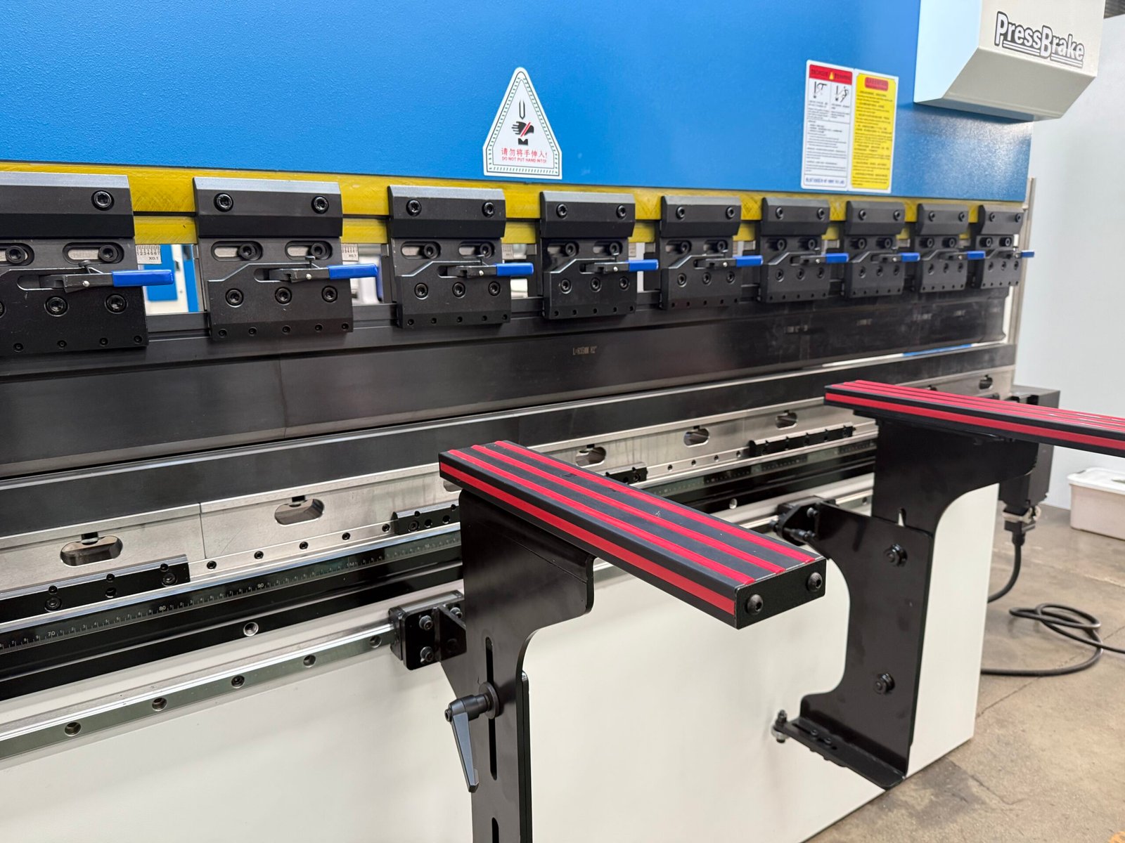
For every bend, identify the physical feature that establishes the position. The sequence record must show that the feature remains accessible and suitable at that stage. A contact point from the flat blank is rejected after an earlier bend when it no longer reaches the specified gauge contact.
Use this sequence record during the desk analysis:
| Field | Required entry / source |
|---|---|
| Bend identity | Drawing feature and direction |
| Incoming state | Which features have already been formed |
| Tool station | Exact punch, die and segment arrangement |
| Position reference | Intended edge or feature and gauge contacts |
| Clearance evidence | Simulation state or reviewed geometry showing the motion |
| Handling / removal | Approved support and the next positioning or withdrawal path |
| Inspection point | Relevant dimension or angle and when it can be checked |
| Unresolved issue | Named obstruction, missing data or required trial |
This is a proposed process-control template. Populate it with the machine supplier or qualified programmer; it does not assume that every machine supports the same gauge motions or contact strategy.
Pay particular attention to dimensions that depend on several bends. Decide with the drawing owner which features are the controlling datums and which intermediate checks protect them. Do not quietly change a datum or loosen a tolerance to make a difficult sequence appear acceptable.
Tooling Changes Invalidate the Previous Sequence Result
A gooseneck profile or a different tool arrangement resolves a collision only when the new configuration passes its rated-load, geometry and compatibility limits. Greater clearance is not a license to exceed the tooling or machine limits.
Segmented tooling provides useful installed-length choices for box work, and specialized end segments serve particular return-flange geometries when their documented profiles clear the actual part. WILA’s catalog illustrates these tooling options. Suitability still depends on the actual profile and part. WILA tooling catalog.
When the proposal changes tooling, require a new sequence validation rather than accepting a catalog image as proof. Changing tool height or the punch profile invalidates any earlier clearance result that used the previous geometry.
Force and tooling-load checks remain separate requirements. A sequence with clear access is rejected when the selected forming method exceeds the machine or tooling rating (source: HORISTAR press brake tonnage guide). Use the machine and tooling manufacturers’ ratings for the proposed setup.
Prove Removal Before Releasing the Final Bend
Do not stop the analysis at the final angle. Bystronic specifically notes the extraction difficulty that arises with some four-sided parts containing return flanges. Bystronic press brake tool-selection guidance.
Show the completed part moving clear of the actual installed tools and surrounding machine geometry. Include the required opening, any planned reorientation and the available handling space. A removal path that exists only with an omitted holder or an unrealistic tool model has not been demonstrated.
If removal depends on a special tooling arrangement, have the supplier document its intended use and approved procedure (source: WILA tooling catalog). Do not improvise by reaching into a hazardous area, bypassing safeguards or releasing tooling outside the manufacturer’s procedure.
When the Part or Fabrication Route Must Change
If no reviewed combination of sequence and available tooling resolves the obstruction, return the issue to design and manufacturing engineering. The design team then selects among a changed flange detail, different tooling or a split fabrication route followed by joining, based on the failed state and product requirements.
These alternatives are design decisions, not operator workarounds. A joined construction changes the validation basis for strength, distortion, appearance, finishing and inspection. Approved Sheet Metal’s deep-part design guidance emphasizes these consequences when deep parts are split into multiple pieces.
Submit the failed state and the requirement it violates with each proposed revision. That gives the drawing owner a concrete choice instead of an unexplained request to “make the box easier to bend.”
Worked Static-Clearance Calculation
Use a simple clearance budget only as an early rejection screen:
Remaining static clearance = specified open height - installed tool-stack height - maximum intermediate-part envelope (source: original screening formula defined for this article).
Illustrative substitution: 520 mm - 300 mm - 205 mm = 15 mm (source: original illustrative arithmetic). The result is 15 mm of nominal static clearance under invented inputs (source: the displayed substitution). A positive result is not approval: release requires the remaining clearance to exceed the supplier-required motion and safety margin, plus a full dynamic collision validation and demonstrated removal path. A result at or below that required margin rejects the setup before a trial. The recommendation is to reject any setup whose calculated remainder does not exceed that documented supplier margin.
Source: original illustrative calculation using invented dimensions solely to demonstrate the screening method; these are not HORISTAR machine specifications or customer results.
Release Checklist and RFQ Inputs
Before accepting a box-part forming proposal, require the evidence package to include:
- The exact drawing revision, material specification and finished-part requirements.
- The candidate sequence and all intermediate part states.
- The actual machine, punch, die, holder and segment configuration.
- Gauge contacts and approved handling arrangements for each bend (source: supplier setup documentation for the quoted configuration).
- Collision validation through motion, plus the final removal path.
- Separate force, tooling-rating and machine-compatibility checks.
- A representative sample trial and an inspection plan agreed in advance.
- A record of unresolved assumptions, with no release until critical issues are closed.
A software simulation does not itself prove production capability. A sample trial must measure the agreed dimensions and demonstrate the handling method under the approved setup, with results retained against the same drawing and tooling revisions (source: original acceptance method defined by this article).
The RFQ input list is: finished 3D model, released drawing revision, material specification, thickness, bend radii, critical tolerances, expected batch mix and any required handling constraints. Send those inputs with a HORISTAR press brake inquiry and request one reviewed package covering the machine, installed tooling, bend sequence, gauge contacts, full-motion clearance and completed-part removal. The useful deliverable is an evidenced forming route; axis count alone does not prove that a box is bendable.
Contact HORISTAR engineering support with the model and drawing package to request a configuration-specific forming-route assessment.